Ammonia spraying control system

A control system and control unit technology, applied in the field of denitrification, can solve the problems of increased pressure of ammonia injection pipe, agglomeration of slag, and affecting the quality of denitrification, so as to avoid pressure increase, uniform distribution and improve quality

Inactive Publication Date: 2019-10-08
北新建材(苏州)有限公司 +1
View PDF8 Cites 1 Cited by
  • Summary
  • Abstract
  • Description
  • Claims
  • Application Information

AI Technical Summary

Problems solved by technology

[0006] (1) In the high temperature environment of the fluidized fluidized furnace, the ammonia water will evaporate immediately after spraying out, and the cinder in the furnace will not be agglomerated. However, when the production line stops burning coal due to a failure, the denitration system will continue to spray ammonia water into the furnace, and the ammonia water cannot Evaporation effectively leads to agglomeration of slag, affecting coal burning and slag discharge;
[0007] (2) Most of the existing ammonia injection devices can only spray ammonia in one direction of the fluidized furnace when injecting ammonia, so that the ammonia gas is unevenly distributed in the fluidized furnace, which affects the quality of denitrification;
[0008] (3) Because the ammonia injection pipe of the ammonia injection device is connected to the fluidized furnace, the temperature is very high, and the ammonia water is likely to evaporate before entering the fluidized furnace, which increases the pressure in the ammonia injection pipe and affects the subsequent spraying of ammonia water

Method used


Image

  • Ammonia spraying control system
  • Ammonia spraying control system
  • Ammonia spraying control system

Examples


Embodiment Construction

[0034] The implementation mode of the present invention is illustrated by specific specific examples below, and those who are familiar with this technology can easily understand other advantages and effects of the present invention from the contents disclosed in this description. Obviously, the described embodiments are a part of the present invention. , but not all examples. Based on the embodiments of the present invention, all other embodiments obtained by persons of ordinary skill in the art without making creative efforts belong to the protection scope of the present invention.

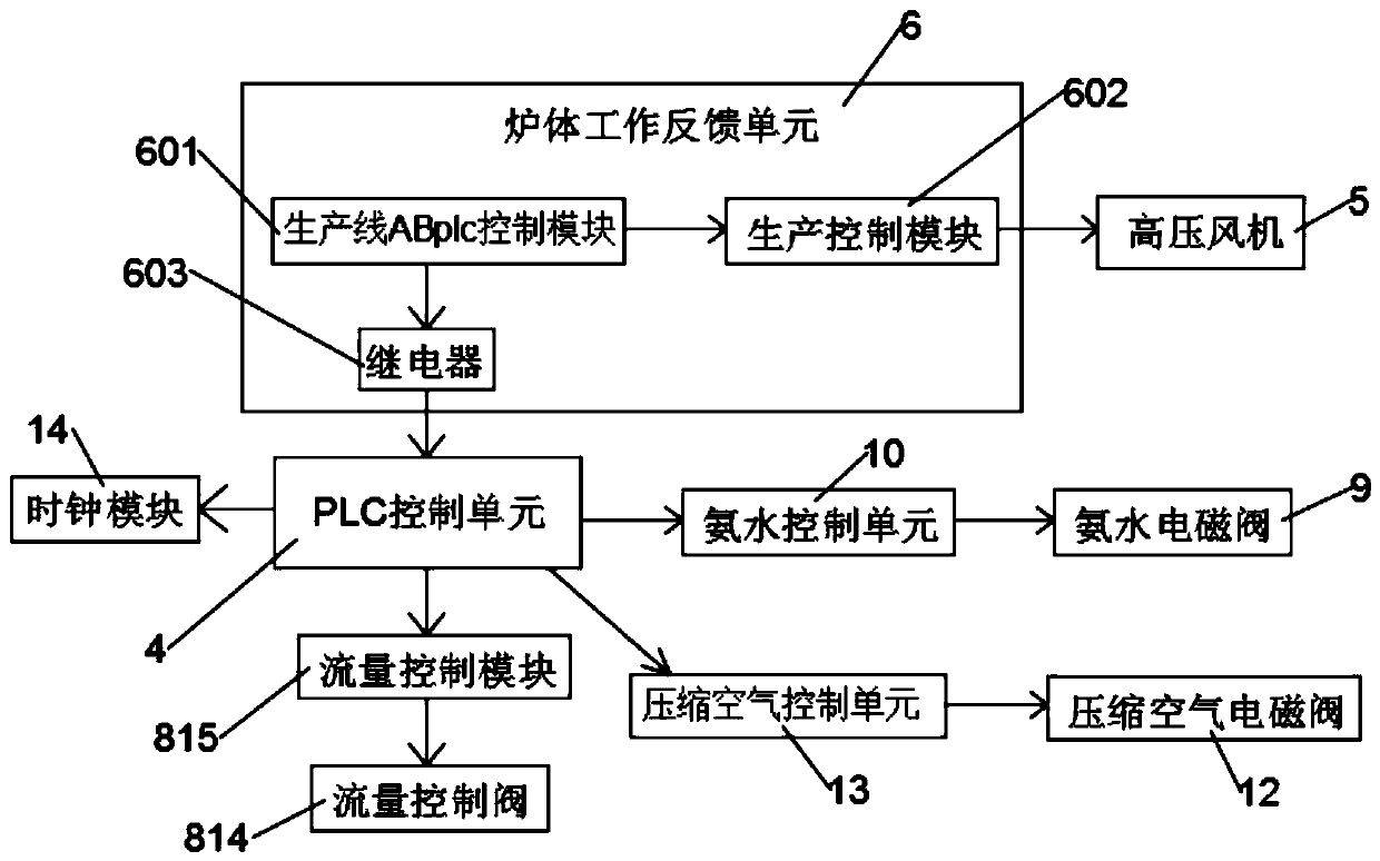
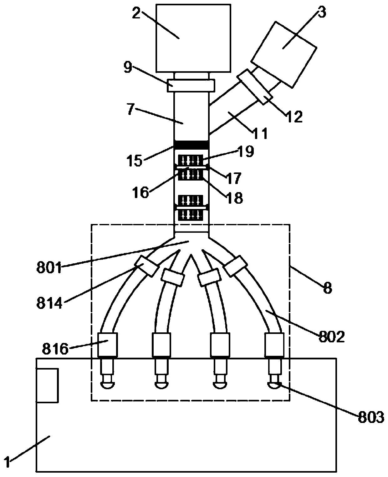
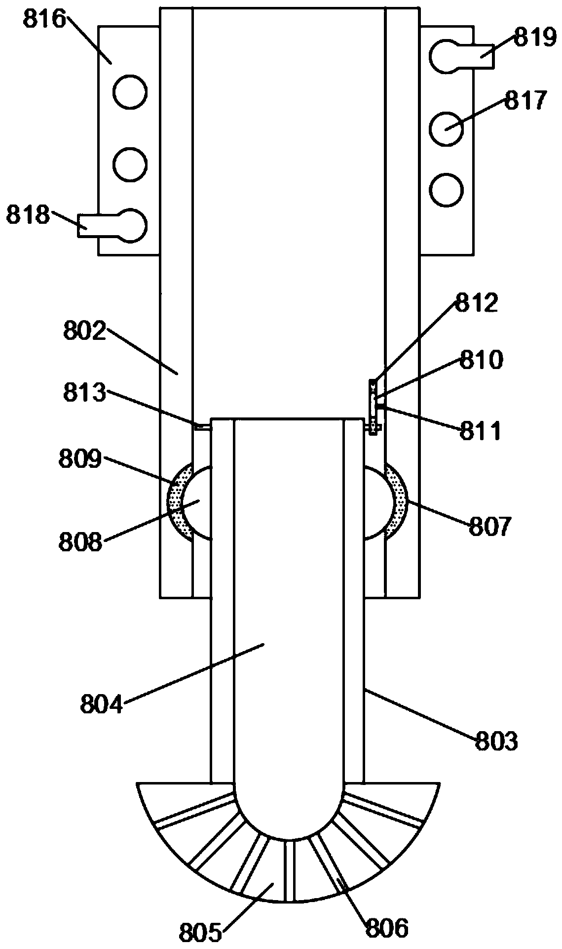
[0035] Such as Figure 1 to Figure 3 As shown, the present invention provides an ammonia injection control system, comprising a fluidized furnace body 1, an ammonia water pump 2, an air compression pump 3 and a PLC control unit 4, a high-pressure fan 5 is installed on the fluidized furnace body 1, and the high-pressure fan 5 passes through the furnace body The work feedback unit 6 is connected w...


PUM


Abstract

An embodiment of the invention discloses an ammonia spraying control system which comprises a boiling furnace, an ammonia water pump, an air compressor pump and a PLC (programmable logic controller) control unit. A high-pressure fan is mounted on the boiling furnace and connected with the PLC control unit through a furnace working feedback unit, an ammonia water pipe is connected at the output endof the ammonia water pump and connected with the boiling furnace through a uniform spraying structure, and a compressed air pipe is connected at the output end of the air compressor pump and connected with the ammonia water pipe. According to the ammonia spraying control system, ammonia water can be intelligently sprayed, an ammonia spraying device can be automatically started when the furnace isstarted, the ammonia spraying device can automatically stop when the furnace is pressed due to failure of a production line or other reasons, caking of slag in the boiling furnace is avoided, the ammonia water can be sprayed to various directions in the boiling furnace, and ammonia gas is more uniformly distributed in the boiling furnace. Besides, according to the system, the ammonia water cannotbe evaporated before entering the boiling furnace, and the influence of increasing of pressure in an ammonia spraying pipe on follow-up spraying of the ammonia water is avoided.

Description

technical field [0001] Embodiments of the present invention relate to the technical field of denitrification, and in particular to an ammonia injection control system. Background technique [0002] Industrial waste gas contains a large amount of sulfur dioxide and nitrogen oxides. Desulfurization is to remove sulfur dioxide in the flue gas, and denitrification is mainly to remove nitrogen oxides in the flue gas. These two substances will form acid rain when they enter the atmosphere. The harm of acid rain to human beings Very large, coal-fueled flue gas contains these substances, especially in thermal power plants. In order to prevent the excessive NOx pollution of the environment after coal combustion in the boiler, the coal should be denitrified. [0003] The denitrification is divided into denitrification before combustion, denitrification during combustion, and denitrification after combustion. There are two types of out-of-stock technical measures: one is to control fr...

Claims


Application Information

Patent Timeline
Patent Type & Authority Applications(China)
IPC IPC(8): B01D53/90B01D53/56
CPCB01D53/8625B01D53/90B01D2251/206
Inventor 鲁旭刘晨周继明刘伟向清昌王浩然邱珂
Owner 北新建材(苏州)有限公司
Why Eureka
Try Eureka