Model predictive current control method for open-winding permanent magnet synchronous motor
A technology of permanent magnet synchronization and model prediction, which is applied in motor generator control, electronic commutation motor control, current controller, etc. The effect of simple structure and excellent drive output performance
- Summary
- Abstract
- Description
- Claims
- Application Information
AI Technical Summary
Problems solved by technology
Method used
Image
Examples
specific Embodiment approach 1
[0049] DETAILED DESCRIPTION - A model predictive current control method for an open-winding permanent magnet synchronous motor, comprising the following steps:
[0050] Step a. establishes the mathematical model of open-winding permanent magnet synchronous motor;
[0051] Step b. Computing and synthesizing the basic space voltage vector;
[0052] Step c. performing current prediction on the open-winding permanent magnet synchronous motor;
[0053] Step d. Bring the current prediction value at k+2 moment into the vector screening module;
[0054] Step e. Applying the switching state of the synthesized basic space voltage vector with the minimum vector screening value to the converter to drive the motor system.
specific Embodiment approach 2
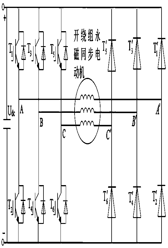
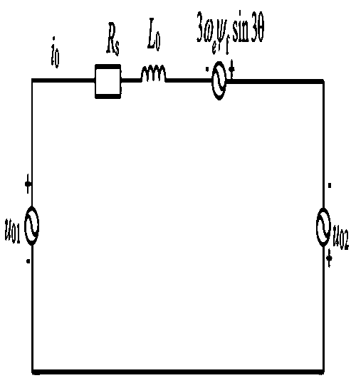
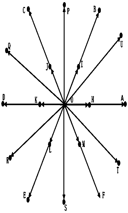
[0055] Embodiment 2 A model predictive current control method for an open-winding permanent magnet synchronous motor, such as figure 1 , figure 2As shown, it includes: a controllable converter module 2, an uncontrollable converter module 3, a current detection module 8, an AC voltage detection module 6, a speed sensor module 7 connected to an open-winding permanent magnet synchronous motor module 4, and a controllable converter module 2 generates a controllable voltage vector set, the uncontrollable converter module 3 generates an uncontrollable voltage vector set, the controllable voltage vector set and the uncontrollable voltage vector set are converted into a basic space voltage vector module 9 to drive the open-winding permanent magnet synchronous motor module 4, The controllable converter module 2 and the uncontrollable converter module 3 are connected to the open-winding permanent magnet synchronous motor module 4, and since the converters on both sides have a common DC...
specific Embodiment approach 3
[0060] Specific Embodiment Three As the open-winding permanent magnet synchronous motor of the present invention:
[0061] The voltage equation of an open-winding permanent magnet synchronous motor:
[0062]
[0063] where u a , u b , u c Indicates the terminal voltage of phase a, phase b and phase c of the motor, e a 、e b 、e c Indicates the electromotive force of phase a, phase b and phase c. u a1 , u b1 , u c1 Indicates the a-phase, b-phase and c-phase voltages output by the controllable converter, u a2 , u b2 , u c2 Indicates the voltage of phase a, phase b and phase c output by the uncontrollable converter, i a i b i c Indicates the components of phase a, phase b and phase c of the stator current, R s Represents stator resistance, M represents mutual inductance, and L represents self-inductance. Transform the voltage equation in the three-phase stationary coordinate system in formula (1) into the synchronous rotating coordinate system with the transforma...
PUM
 Abstract
Description
Claims
Application Information
 - R&D
- Intellectual Property
- Life Sciences
- Materials
- Tech Scout
- Unparalleled Data Quality
- Higher Quality Content
- 60% Fewer Hallucinations
Browse by: Latest US Patents, China's latest patents, Technical Efficacy Thesaurus, Application Domain, Technology Topic, Popular Technical Reports.
© 2025 PatSnap. All rights reserved.Legal|Privacy policy|Modern Slavery Act Transparency Statement|Sitemap|About US| Contact US: help@patsnap.com


