Method for efficient and energy-saving sludge treatment

A technology for sludge treatment, high efficiency and energy saving, applied in sludge treatment, water/sludge/sewage treatment, pyrolysis treatment of sludge, etc. It can solve the problems of about 60%, and achieve the effect of eliminating water hammer phenomenon, facilitating subsequent disposal, and reducing process links

Pending Publication Date: 2019-10-18
SHENZHEN ECO SOLUTION TECH CORP
View PDF0 Cites 3 Cited by
  • Summary
  • Abstract
  • Description
  • Claims
  • Application Information

AI Technical Summary

Problems solved by technology

[0002] At present, the dry weight of sludge treated by sewage treatment plants in my country is about 1.4 million tons per year, and it is increasing at a rate of more than 10% every year; moreover, sludge contains a large amount of harmful substances such as heavy metals and pathogenic bacteria, which is harmful to the environment; It can be seen that the problem of environmental pollution caused by sludge is becoming more and more prominent, which has caused great safety hazards, environmental hazards and economic burdens for the society. The thermal hydrolysis digestion process is a method to reduce, recycle and stabilize sludge. and secure processing technology
[0003] Existing sludge plants often put a certain amount of sludge into the thermal hydrolysis tank after mixing, and keep it under high temperature and high pressure for a certain period of time, so that the sludge thermal hydrolysis is completed, and then the sludge is discharged and transported To the next treatment link, in this way, the mixing efficiency of steam and sludge is slow, the treatment time is long, the energy consumption is high, and the energy utilization rate is low; the land occupation is large, the investment is high; the operation and maintenance cost is high; the moisture content of the mechanically dewatered cake It can only reach about 60%; thereby increasing the cost of thermal hydrolysis, and it is cumbersome to clean up after the treatment is completed, which greatly increases the work intensity of the staff

Method used


Image

  • Method for efficient and energy-saving sludge treatment
  • Method for efficient and energy-saving sludge treatment
  • Method for efficient and energy-saving sludge treatment

Examples


Embodiment 1

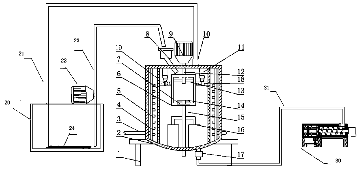
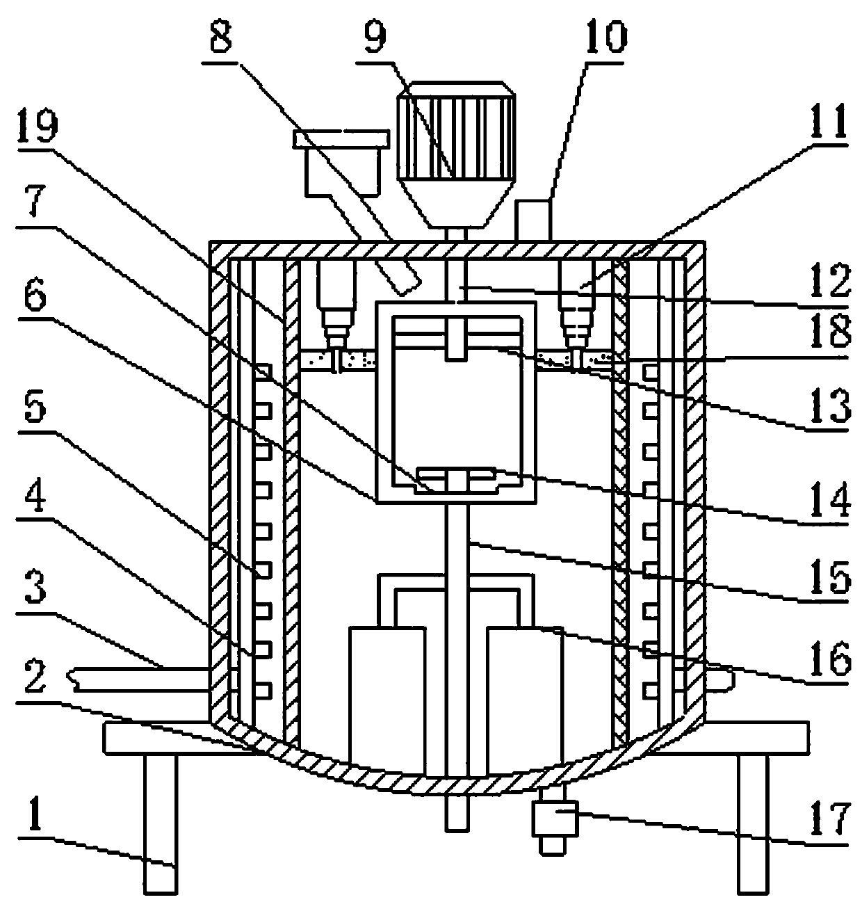
[0038] The sludge with a moisture content of 80% is first pumped to the preheating unit through a screw pump, and the screw pump is turned off when the mud reaches the set level. An aeration pipe is set in the preheating unit, and the aeration hole diameter is 1.8mm. The preheating of the mud is completed , The hot mud is pumped to the reactor through a pump. After the mud enters the reactor, the boiler provides continuous and stable high-pressure saturated steam (pressure 1.1-1.2Mpa) to the reactor to heat the sludge in the reactor and inject saturated steam 30 minutes, then stop the steam injection and keep it for 20 minutes; then open the pressure relief valve to start exhaust and pressure relief. The high-pressure steam discharged from the reactor enters the preheating unit through the aeration tube to fully preheat the raw mud to 60°C. The form forms a closed circuit. When the exhaust is completed, the discharge valve is opened to discharge the mud after thermal hydrolysis....

Embodiment 2

[0040] The sludge with a moisture content of 85% is first pumped to the preheating unit through a screw pump, and the screw pump is turned off when the mud reaches the set level. An aeration pipe is set in the preheating unit, and the aeration hole diameter is 2.5mm. The preheating of the mud is completed , The hot mud is pumped to the reactor through a pump. After the mud enters the reactor, the boiler provides continuous and stable high-pressure saturated steam (pressure 1.2-1.3Mpa) to the reactor to heat the sludge in the reactor and inject saturated steam After 25 minutes, stop the steam injection and keep it for 10 minutes; then open the pressure relief valve to start exhaust and pressure relief. The high-pressure steam discharged from the reactor enters the preheating unit through the aeration tube to fully preheat the raw mud to 65°C. The form forms a closed circuit. When the exhaust is completed, the discharge valve is opened to discharge the mud after thermal hydrolysis...

Embodiment 3

[0042] The sludge with a water content of 90% is first pumped to the preheating unit through a screw pump. When the mud reaches the set level, the screw pump is turned off. The preheating unit is equipped with an aeration pipe. After the preheating of the mud is completed, the hot mud is pumped to In the reactor, after the mud enters the reactor, the boiler provides continuous and stable high-pressure saturated steam (pressure 1.3-1.4Mpa) to the reactor, heats the sludge in the reactor, and injects saturated steam for 20 minutes, and then stops the steam injection. Hold for 10 minutes; then open the pressure relief valve to start exhaust and pressure relief. The high-pressure steam discharged from the reactor enters the preheating unit through the aeration tube to fully preheat the raw mud to over 70°C, forming a closed circuit in this way. At the end, open the discharge valve to discharge the thermally hydrolyzed mud. The mud in the preheating unit is pumped into the reactor an...


PUM


Abstract

The invention discloses a method and device for efficient and energy-saving sludge treatment. The method of sludge treatment comprises the steps: the sludge first enters the preheating unit, and afterpreheating to 60 degrees or more, directly enters the thermal hydrolysis unit, and the high temperature pressurized steam generated after the end of the thermal hydrolysis is returned to the preheating unit to preheat the sludge. The device is a thermal hydrolysis device, including a mounting seat, a tank body, an air inlet pipe, an air guiding pipe, a nozzle, a sieve cylinder, a card slot, a loading bin, a motor, an exhaust pipe, a multi-stage electric push rod, a shaft rod, a connecting rod , block, rotating rod, mixing blade, discharge tube, brush and filter net. The method and the deviceaccelerate the speed of thermal hydrolysis, can make the steam and sludge mixing effect better, and also save the cost, greatly improve the work efficiency, reduce the work intensity of the staff, andalso enhance the work. Practicality.

Description

Technical field [0001] The invention belongs to the technical field of sludge treatment application, and relates to a sludge treatment method and device, in particular to a high-efficiency and energy-saving sludge treatment method and device. Background technique [0002] At present, the dry weight of sludge processed by my country's sewage treatment plants is about 1.4 million tons per year, and the annual growth rate is more than 10%; moreover, the sludge contains a lot of heavy metals, pathogens and other harmful substances, which are harmful to the environment; It can be seen that the environmental pollution caused by sludge is becoming more and more prominent, causing greater safety hazards, environmental hazards and economic burdens to the society. The thermal hydrolysis digestion process is a way to reduce, recycle, and stabilize sludge. And safe processing technology. [0003] Existing sludge equipment often mixes a certain amount of sludge into a thermal hydrolysis tank, an...

Claims


Application Information

Patent Timeline
Patent Type & Authority Applications(China)
IPC IPC(8): C02F11/10C02F11/122
CPCC02F11/10C02F11/122
Inventor 黄彤宇
Owner SHENZHEN ECO SOLUTION TECH CORP
Why Eureka
Try Eureka