A Precise Machining Method for Sealing B Ring of Shaft End Parts of Mixer

A processing method and mixer technology, applied in the field of shaft end parts processing, can solve the problems of poor accuracy and low processing efficiency, and achieve the effects of preventing movement, improving production efficiency, and uniform and stable relative position.

Active Publication Date: 2020-12-29
马鞍山万力重工机械制造有限公司
View PDF4 Cites 0 Cited by
  • Summary
  • Abstract
  • Description
  • Claims
  • Application Information

AI Technical Summary

Problems solved by technology

[0006] Aiming at the problem that the drilling machine equipment in the prior art cannot directly process the installation hole of the seal B ring of the shaft end part, and the processing efficiency is low and the accuracy is poor, the present invention provides a precise machining method for the seal B ring of the shaft end part of the mixer. The installation hole to be processed of the end piece seal B ring is located perpendicular to the horizontal plane. By setting the guide hole, the drill bit can quickly and accurately locate the position of the installation hole to be processed, and then fix the processing tool to prevent the processing tool from moving during the process, ensuring Machining accuracy, no need for scribing marks, improve processing efficiency, high processing pass rate

Method used


Image

  • A Precise Machining Method for Sealing B Ring of Shaft End Parts of Mixer
  • A Precise Machining Method for Sealing B Ring of Shaft End Parts of Mixer
  • A Precise Machining Method for Sealing B Ring of Shaft End Parts of Mixer

Examples


Embodiment 1

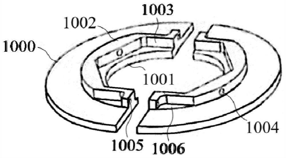
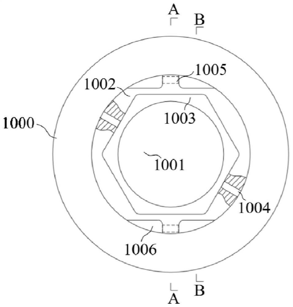
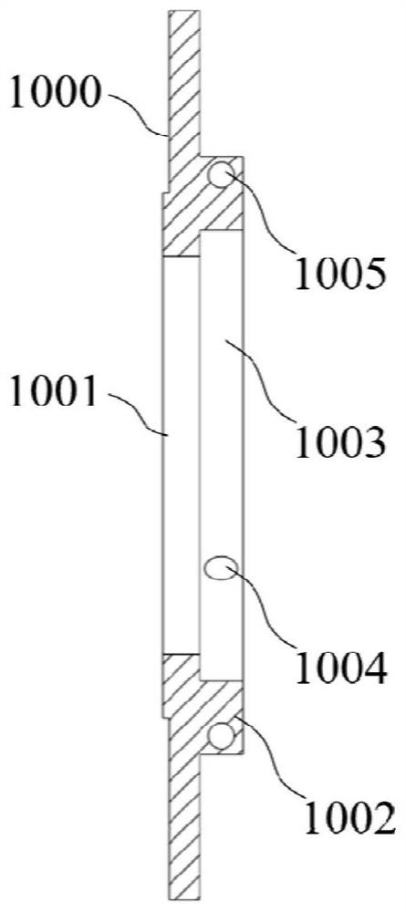
[0097] Such as figure 1 , figure 2 , image 3 with Figure 4 As shown, it is a schematic structural diagram of the seal B ring of the shaft end part. The processing equipment of this embodiment is designed based on the installation hole 1 1004 and the installation hole 2 1005 of the shaft end part seal B ring.

[0098] Such as Figure 13 with 15 As shown, the present embodiment makes improvements on the basis of the existing drilling machine. The main body of the drilling machine 100 and the workbench 200 are existing structures. In this embodiment, a T-shaped groove 210 is provided downwards on the upper surface of the workbench 200. A plurality of T-shaped grooves 210 are arranged side by side on the upper surface of the workbench 200 .

[0099] Such as Figure 5 , Image 6 with Figure 7 As shown, the present embodiment is also equipped with a processing tool 300. The mounting seat 1 of the processing tool 300 is an inverted T-shaped structure composed of a horizon...

Embodiment 2

[0106] This embodiment is modified on the basis of embodiment 1. The difference from embodiment 1 is that the fastening device of this embodiment is as Figure 12 As shown, it includes a threaded rod 8 and a knob 9. The threaded rod 8 is in the shape of a long rod, and the side wall is provided with a threaded structure. The knob 9 is in the shape of a disc. The diameter of the through hole 1001 also includes a long rod-shaped fastening rod 90 whose length is greater than the diameter of the circular through hole 1001 of the seal B ring of the shaft end piece. The solid rod 90 is placed between the knob 9 and the sealing B ring base 1000 of the shaft end piece to be processed, and the concave structure is set on the threaded rod 8, and the knob 9 is tightened, and the knob 9 acts on the fastening rod 90 to further process the shaft end piece Seal the B ring for fastening.

Embodiment 3

[0108] A precise machining method for the seal B ring of the shaft end part of the mixer, the steps are as follows:

[0109] 1. Assembly:

[0110] a. Unscrew the knob 9, align the regular hexagonal counterbore 1003 of the seal B ring of the shaft end piece with the fixed block 1 for assembly, wherein the installation hole 1005 of the seal B ring of the shaft end piece to be processed is located at the positioning block 1 5 or directly below the positioning block 2 6;

[0111] b. Unscrew the knob 9, align the regular hexagonal counterbore 1003 of the seal B ring of the shaft end piece with the fixing block 2 3 for assembly, wherein, the installation hole 1005 of the seal B ring of the shaft end piece is located at the positioning block 3 directly below 7;

[0112] 2. Fastening:

[0113] Screw in the knob 9 on the threaded rod 8, and rotate the knob 9 to make the knob 9 contact with the base body 1000 of the seal B ring of the shaft end piece;

[0114] 3. Alignment:

[0115...


PUM


Abstract

The invention discloses a precise machining method of a shaft end piece sealing ring B of a stirrer, and belongs to the field of shaft end piece machining. According to the method, the to-be-machinedshaft end piece sealing ring B is assembled on a machining tool, a to-be-machined installation hole of the shaft end piece sealing ring B is perpendicular to the horizontal plane, by forming a guide hole, the position of the to-be-machined installation hole can be located fast and accurately, then by fixing the machining tool, the machining tool is prevented from moving in the machining process, and the machining precision is guaranteed. By means of the method, machining of the installation hole can be conducted without line marking, the machining efficiency is improved, in addition, the machining precision is high, and the machining qualification rate is high.

Description

technical field [0001] The invention belongs to the field of shaft end piece processing, and more specifically relates to a precise machining method for a seal B ring of a shaft end piece of a mixer. Background technique [0002] Twin-shaft mixer is a commonly used equipment in the field of construction. It is used for mixing various powdery materials. During the use of the mixer, the drive shaft is installed inside and outside the equipment, and there is an assembly gap between it and the fixing parts. The material in the mixer Materials such as slurry will leak out through this gap, which will affect the normal use of the mixing equipment. Therefore, shaft end seals are usually required to seal the shaft end assembly gap to prevent leakage. [0003] The shaft end seal B ring is a component of the shaft end seal kit used in twin-shaft mixers. It is an industry standard part, and its shape and structure are as follows: figure 1 , figure 2 , image 3 with Figure 4 As sh...

Claims


Application Information

Patent Timeline
Patent Type & Authority Patents(China)
IPC IPC(8): B23B35/00B23B41/00B23Q3/06
CPCB23B35/00B23B41/00B23Q3/062
Inventor 陶鹏飞
Owner 马鞍山万力重工机械制造有限公司
Why Eureka
Try Eureka