Cooling flame low nitrogen combustion device and combustion method thereof

A low-nitrogen combustion and flame technology, applied in the direction of combustion method, burner, combustion type, etc., can solve the problems of fast propagation speed of fully premixed flame, inability to prevent tempering, and a large amount of nitrogen oxides, so as to avoid the concentration of high temperature areas. , Solve the effect of easy tempering and reducing the formation of nitrogen oxides

Active Publication Date: 2019-10-22
江苏泷涛环境技术有限公司
View PDF7 Cites 5 Cited by
  • Summary
  • Abstract
  • Description
  • Claims
  • Application Information

AI Technical Summary

Problems solved by technology

At present, my country's fully premixed condensing technology is not yet mature, such as the water-cooled surface combustion low-nitrogen burner disclosed in the patent CN108443876A, the boiler with it and its applicable method, the combustion-supporting air and natural gas are completely mixed and then evenly overflow through the gap of the spiral cooling pipe and The ignition gun cooperates with the combustion,

Method used


Image

  • Cooling flame low nitrogen combustion device and combustion method thereof
  • Cooling flame low nitrogen combustion device and combustion method thereof
  • Cooling flame low nitrogen combustion device and combustion method thereof

Examples


Embodiment 1

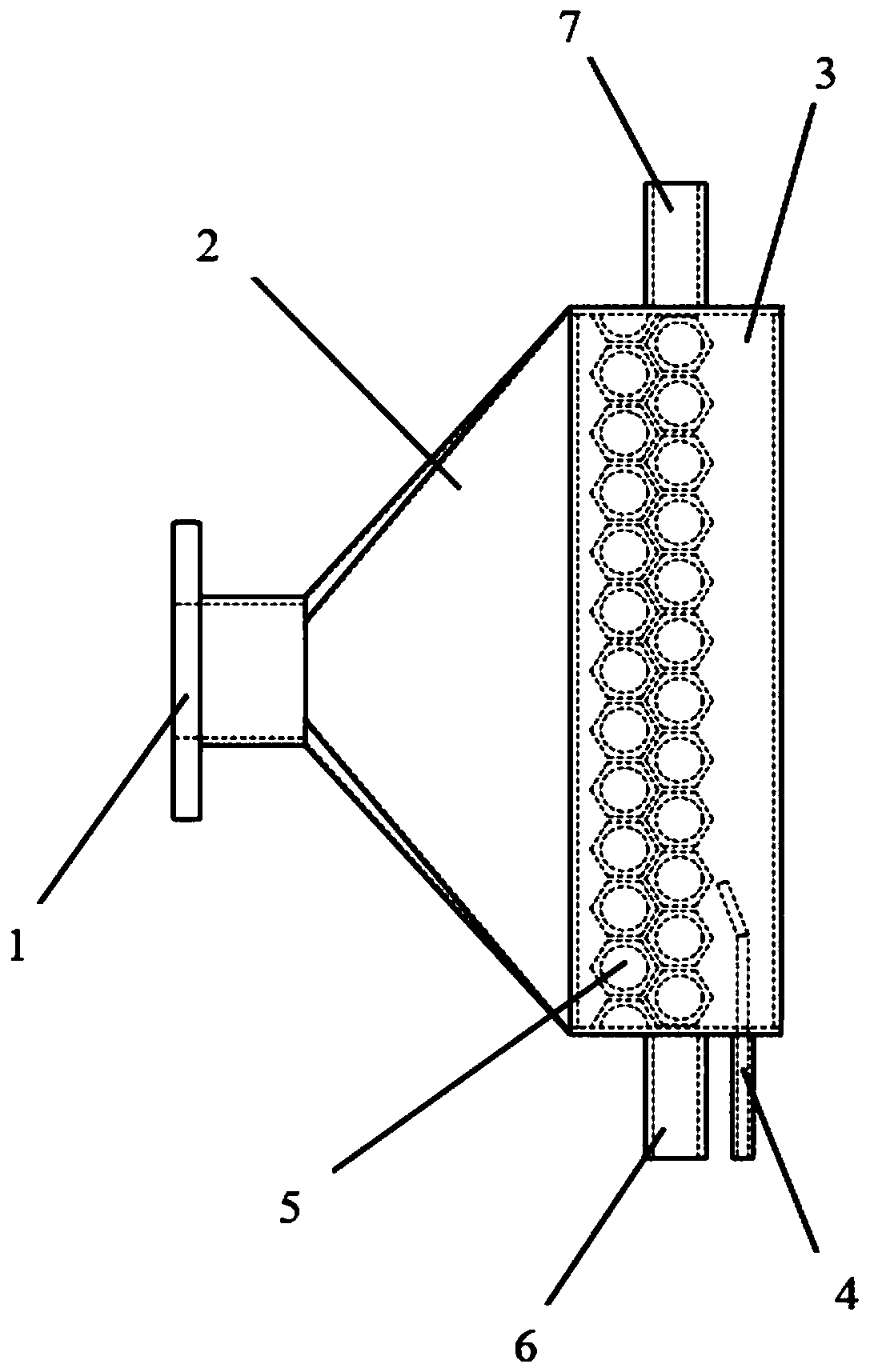
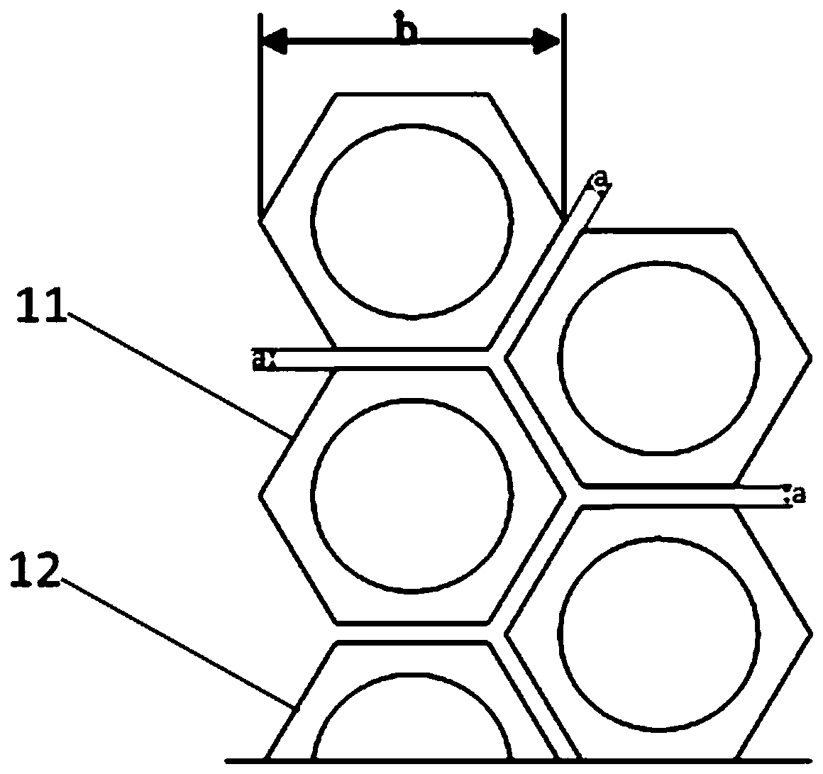
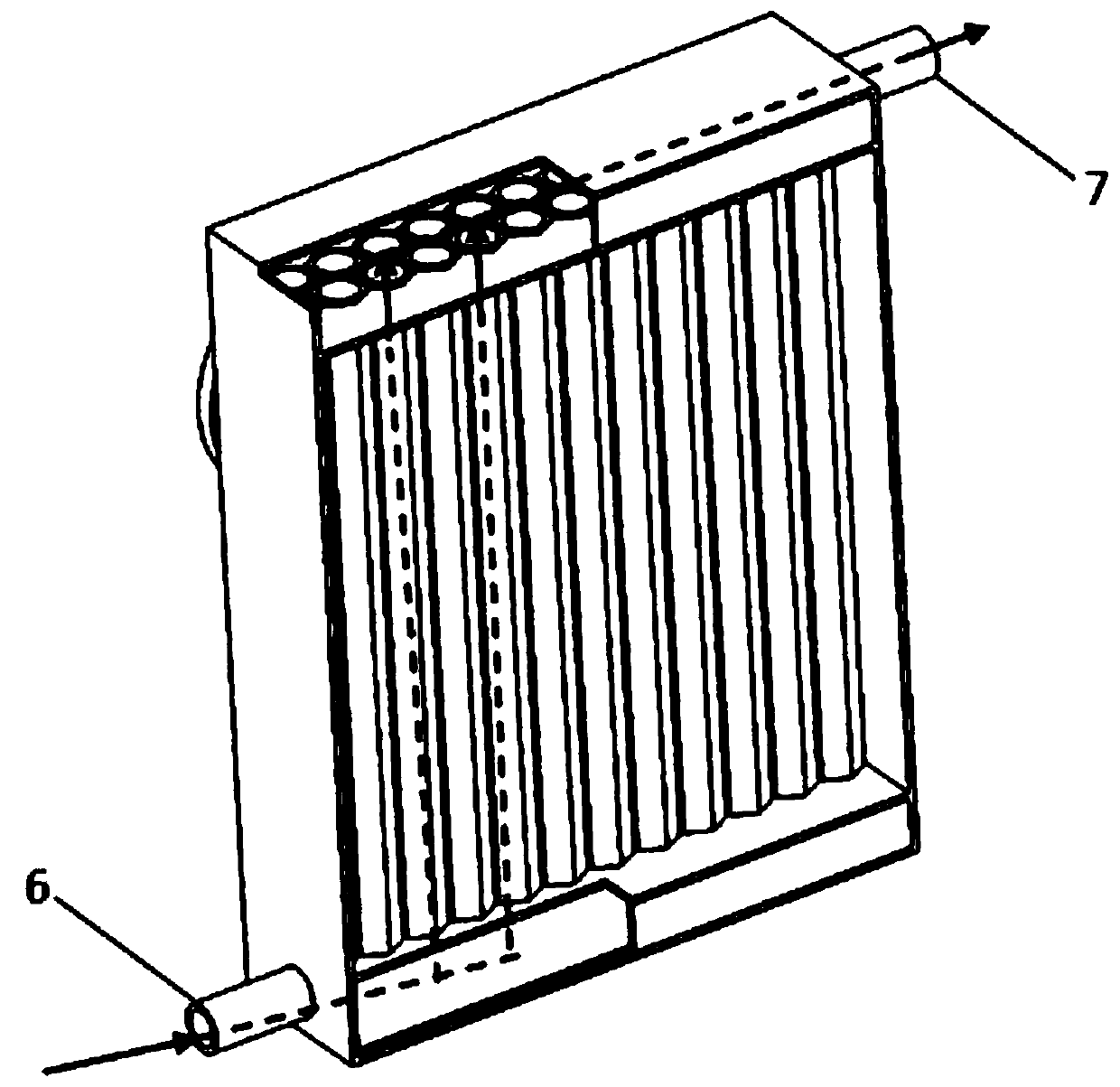
[0051] This embodiment provides a cooling flame low nitrogen combustion device, such as figure 1 As shown, it includes a premixed gas inlet 1, a distributing chamber 2, a combustion chamber 3, a first cooling liquid inlet 6 and a first cooling liquid outlet 7, and the combustion chamber 3 is sequentially provided with the first cooling liquid along the flow direction of the premixed gas A heat exchange tube assembly 5 and an igniter 4 . In this embodiment, the gas distributing chamber 2 is a trumpet-shaped structure, its narrow end is connected to the premixed gas inlet 1, and its wide end is connected to the combustion chamber 3; the first heat exchange tube assembly 5 It consists of two sets of vertical first heat exchange tube rows arranged in parallel. The first heat exchange tube row on the left side is close to the gas distribution chamber 2. It is formed by 11 outer hexagonal tubes arranged in parallel on the same plane. The right side The first heat exchange tube row ...

Embodiment 2

[0060] As another embodiment of the present invention, it is similar to Embodiment 1, except that: Figure 4 As shown, the combustion chamber 3 of the second embodiment also includes a second heat exchange tube assembly 8, and the second heat exchange tube assembly 8 is arranged behind the igniter 4 along the flow direction of the premixed gas. The distance between the heat exchange tube assembly 5 and the second heat exchange tube assembly 8 is 42mm.

[0061] In this embodiment, the second heat exchange tube assembly 8 is formed by three groups of second heat exchange tube rows arranged in parallel and at intervals, and the three groups of second heat exchange tube rows are respectively composed of 11, 10 and 11 The second heat exchange tubes are formed in parallel and spaced arrays on the same plane, and three adjacent heat exchange tubes are arranged in a triangular shape on a transverse cross section.

[0062] The combustion method of the cooling flame low-nitrogen combus...


PUM


Abstract

The invention relates to a cooling flame low nitrogen combustion device. The device comprises a premixed gas inlet and a combustion chamber, wherein a first heat exchange tube assembly and an igniterin the flow direction of premixed gas are successively arranged in the combustion chamber; the first heat exchange tube assembly is composed of a plurality of outer hexagonal tubes arranged in parallel, and gaps are formed between the adjacent outer hexagonal tubes to allow the premixed gas to pass through; and the position of the igniter opposite to the first heat exchange tube assembly is set insuch a way that the igniter can directly ignite the premixed gas passing through the gaps. Cooling fluid circulates in the outer hexagonal tubes, and the temperature of a flame is reduced duo to thecold wall effect of the cooling fluid, so that the formation of nitrogen oxides is inhibited; and at the same time, when the flame propagation speed is greater than the air flow speed, and the flame returns into the gaps between the outer hexagonal tubes, the energy of the flame becomes smaller and smaller under the cooling effect of the cooling fluid until the flame goes out in the gaps, so thatthe explosion caused by the tempering phenomenon is avoided.

Description

technical field [0001] The invention relates to the field of combustion devices, in particular to a cooling flame low-nitrogen combustion device and a combustion method thereof. Background technique [0002] In order to strengthen environmental governance, my country once again tightened the emission standards of nitrogen oxides, requiring existing boilers to undergo low-nitrogen transformation and new boilers to adopt low-nitrogen combustion technology to ensure that nitrogen oxide emissions are below 30mg / m 3 the following. [0003] Pre-mixing technology is to mix gas and air in a certain ratio before combustion, and increase the heat-absorbing working medium in the flame area by increasing the excess air coefficient to reduce the temperature of the flame, thereby reducing the formation of nitrogen oxides. The heat exchange condensation technology is to transfer the heat generated by the flame to the water in the heat exchange tube through the heat exchange tube with high...

Claims


Application Information

Patent Timeline
IPC IPC(8): F23D14/02F23D14/74F23D14/82F23D14/26F23D14/46
CPCF23D14/02F23D14/26F23D14/46F23D14/74F23D14/82
Inventor 郭行王高月宋少鹏贺应杰高峰
Owner 江苏泷涛环境技术有限公司
Why Eureka
Try Eureka