Surface plasmon based waveguide band-stop filter

A band-stop filter and surface plasmon technology, applied in the field of micro-nano optics, can solve the problems of high stop-band transmittance, not smooth enough curve, low pass-band transmittance, etc. high effect

Inactive Publication Date: 2019-10-22
GUILIN UNIV OF ELECTRONIC TECH
View PDF3 Cites 2 Cited by
  • Summary
  • Abstract
  • Description
  • Claims
  • Application Information

AI Technical Summary

Problems solved by technology

Although these structures have the advantages of small size, adjustable, and many stop-band modes, there are still disadvantages such as slightly higher transmittance in the stop band, slightly lower transmittance in the pass band, unsmooth curves, and low quality factors.

Method used


Image

  • Surface plasmon based waveguide band-stop filter
  • Surface plasmon based waveguide band-stop filter
  • Surface plasmon based waveguide band-stop filter

Examples


Embodiment Construction

[0020] The present invention will be further explained below in conjunction with the accompanying drawings and this embodiment.

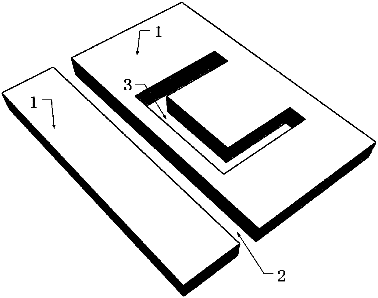
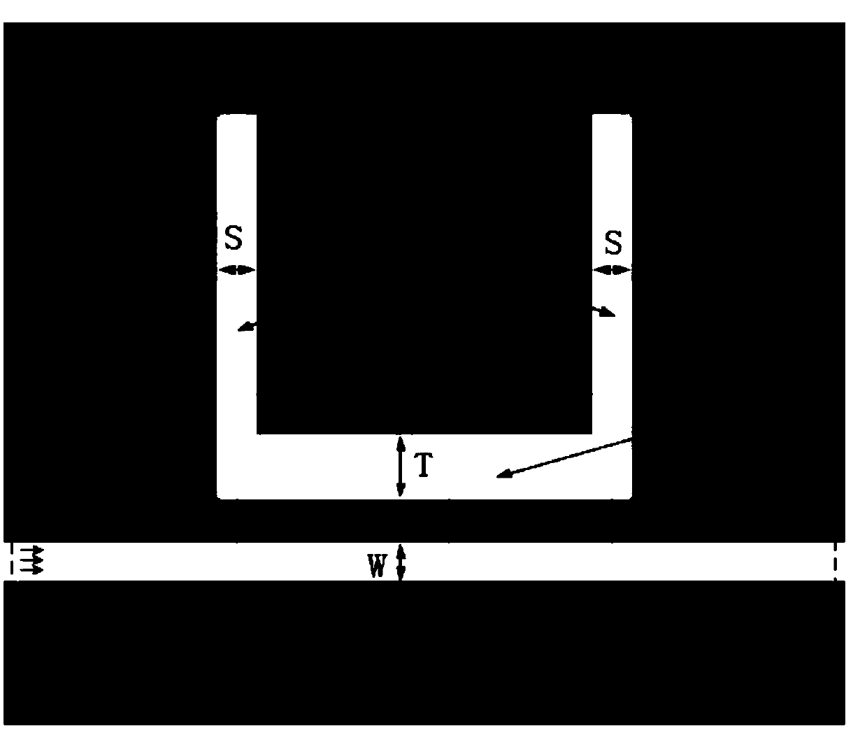
[0021] figure 1 It is a schematic diagram of the three-dimensional structure of the surface plasmon band-stop filter. Including metal film 1, waveguide 2, and resonant cavity 3. In this example, the metal film is a gold film. The three-dimensional structure of the metal film is in the shape of a cuboid. 2000nm. The waveguide cuboid and the resonant cavity square U font structure are embedded in the metal film body, and the filling medium in the waveguide and the resonant cavity is air. The thickness and length of the waveguide and the metal film are equal, and its position is embedded in one-third of the lower side of the metal film. The resonant cavity is embedded in the middle of the metal film in the vertical direction, the shortest distance from the waveguide is 10nm, and the width of the cavity in the two vertical directions is equal to the ...


PUM

PropertyMeasurementUnit
Lengthaaaaaaaaaa
Widthaaaaaaaaaa
Lengthaaaaaaaaaa

Abstract

The invention relates to a surface plasmon based waveguide band-stop filter which is composed of a metal film, waveguide tube and a resonant cavity. The waveguide tube is shaped as a long-strip rectangular hole, the resonant cavity is of a square U shape composed of one horizontal extension hole and two vertical extension holes connected to the horizontal extension hole, the shape and size of theone vertical extension hole are completely the same with those of the other, and each of the horizontal and vertical extension holes is shaped as a long-strip rectangular hole of a regular rectangularshape. The filter is simple in structure, small in packaging size, multi-mode, high in transmissivity, smooth in passband, narrower in stop band, high in quality factor and adjustable. The stop bandwidth can be adjusted by changing a structural parameter. It is proved that the stop band transmittance can be lower than 0.01 and the maximal passband transmittance can reach 0.98 with smooth distribution in the top. The filter can be widely applied in micro nano optical integrated devices.

Description

technical field [0001] The invention relates to the field of micro-nano optics technology, in particular to a surface plasmon waveguide band-stop filter. Background technique [0002] Surface plasmon polaritons (Surface Plasmon Polartions, SPPs) are special electromagnetic surface waves propagating along the metal-dielectric interface. It is a mixed excited state formed by the interaction of free electrons and photons localized on the metal surface. In this interaction, free electrons irradiated by light waves collectively oscillate at the same frequency as their resonance, and the interaction between this surface charge oscillation and the electromagnetic field of light waves constitutes SPPs with unique properties. Surface plasmon polaritons (SPPs) devices are research hotspots and development directions in the world today. [0003] With the development of science and technology, information technology has profoundly affected the way of life of human beings. At the same ...

Claims


Application Information

Patent Timeline
IPC IPC(8): G02B5/00G02B6/122
CPCG02B5/008G02B6/122
Inventor 肖功利杨秀华杨宏艳李海鸥张法碧傅涛孙堂友
Owner GUILIN UNIV OF ELECTRONIC TECH
Why Eureka
Try Eureka