Gate drive circuit

A gate drive circuit and gate drive technology, used in instruments, static indicators, etc., can solve problems such as threshold voltage drift easily and gate drive circuit failure.

Active Publication Date: 2019-10-25
SHENZHEN CHINA STAR OPTOELECTRONICS SEMICON DISPLAY TECH CO LTD
View PDF6 Cites 14 Cited by
  • Summary
  • Abstract
  • Description
  • Claims
  • Application Information

AI Technical Summary

Problems solved by technology

When a transistor works for a long time, especially for an Indium Gallium Zinc Oxide (IGZO) transistor, i

Method used


Image

  • Gate drive circuit
  • Gate drive circuit

Examples


Embodiment Construction

[0019] In order to make the purpose, technical means and effects of the present invention clearer, the present invention will be further elaborated below in conjunction with the accompanying drawings. It should be understood that the embodiments described here are only some, not all, embodiments of the present invention, and are not intended to limit the present invention.

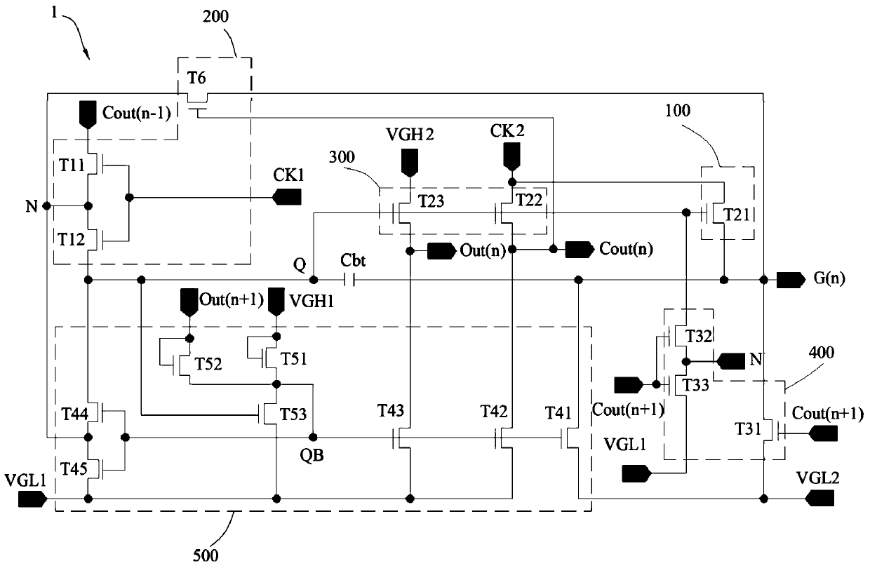
[0020] Please refer to figure 1 , which shows a schematic circuit structure diagram of a gate driving circuit according to an embodiment of the present invention. The gate drive circuit includes a plurality of cascaded gate drive units 1, and the gate drive unit 1 includes a pull-up unit 100, a pull-up control unit 200, a downlink unit 300, a pull-down unit 400, a pull-down sustain unit 500 and a bootstrap capacitor Cbt. In this embodiment, the first clock signal CK1 and the second clock signal CK2 are AC signals with opposite waveforms. Specifically, the second DC low voltage VGL2 is greater than the f...


PUM


Abstract

A gate drive circuit comprises a plurality of gate drive units, comprising a pull-up control unit connected with a first node, a second node, a first clock signal, a scanning signal output end, a current-stage stage transmission signal output end and a preceding-stage transmission signal output end; a pull-down maintaining unit, connected with the first node, the second node, a current-stage feedback signal output end, a next-stage feedback signal output end, a scanning signal output end, a current-stage transmission signal output end, a first direct-current high voltage, a first direct-current low voltage and a second direct-current low voltage; a pull-up unit, connected with the first node, a second clock signal and a scanning signal output end; a downloading unit, connected with the first node, a second clock signal, a second direct-current high voltage, a local-stage feedback signal output end and a local-stage transmission signal output end; a pull-down unit, connected with the first node, the second node, the scanning signal output end, the next-stage cascade signal output end, the first direct-current low voltage and the second direct-current low voltage; and a bootstrap capacitor, one end of the bootstrap capacitor being connected with the first node, and the other end being connected with the scanning signal output end.

Description

technical field [0001] The present invention relates to the field of display technology, in particular to a gate drive circuit for a display panel. Background technique [0002] The gate driver on array (GOA) technology, that is, the row driving technology of the array substrate, is to manufacture the gate scanning driving circuit on the thin film transistor array substrate to realize the driving mode of progressive scanning. [0003] In a conventional gate driving circuit, the node QB is the gate point of the transistor that maintains the output signal at a low level. During the display period of a frame, the node QB is almost kept at a high potential, so that the transistor controlled by the node QB is always on. When a transistor works for a long time, especially for an Indium Gallium Zinc Oxide (IGZO) transistor, its threshold voltage (threshold voltage) tends to drift, resulting in failure of the gate drive circuit. [0004] Therefore, it is necessary to provide a gat...

Claims


Application Information

Patent Timeline
IPC IPC(8): G09G3/20
CPCG09G3/20G09G2310/0267
Inventor 薛炎
Owner SHENZHEN CHINA STAR OPTOELECTRONICS SEMICON DISPLAY TECH CO LTD
Why Eureka
Try Eureka