Bearing-free magnetic flux switching permanent magnet motor rotor eccentric displacement compensation controller

A technology of displacement compensation and magnetic flux switching, which is applied in the field of flywheel energy storage, can solve problems such as rotor vibration and noise, and achieve the effects of ensuring accuracy and reliability, reducing complexity, and eliminating coordinate transformation links

Inactive Publication Date: 2019-10-25
JIANGSU UNIV
View PDF5 Cites 12 Cited by
  • Summary
  • Abstract
  • Description
  • Claims
  • Application Information

AI Technical Summary

Problems solved by technology

[0005] The purpose of the present invention is to solve the problem of rotor vibration and noise caused by the asymmetrical magnetic pull force caused by the eccentricity of the rotor mass in the existing bearingless flux switching permanent magnet motor, and to avoid the complicated process of detecting the rotor magnetic center, according to the rotor eccentric displacement , radial levitation force, and the relationship between the rotor position angle, an adaptive filter based on the least mean square algorithm is used to actively compensate and control the radial displacement of the rotor of the bearingless flux switching motor, thereby offsetting the disadvantage of magnetic eccentricity Consequences, a compensating controller is designed for compensating the rotor eccentric displacement of a bearingless flux switching permanent magnet motor

Method used


Image

  • Bearing-free magnetic flux switching permanent magnet motor rotor eccentric displacement compensation controller
  • Bearing-free magnetic flux switching permanent magnet motor rotor eccentric displacement compensation controller
  • Bearing-free magnetic flux switching permanent magnet motor rotor eccentric displacement compensation controller

Examples


Embodiment Construction

[0025] The rotor eccentric displacement compensation controller of the bearingless magnetic flux switching permanent magnet motor of the present invention will be further described below in conjunction with the accompanying drawings.

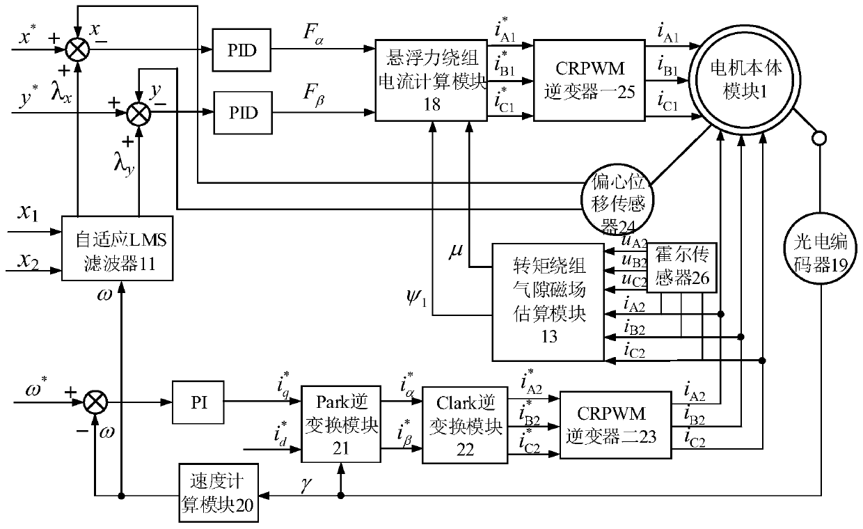
[0026] see figure 1 , the present invention is mainly divided into speed control and suspension force control. The suspension force control part needs to consider the compensation control of rotor eccentric displacement on the basis of the radial displacement control of the rotor in the motor body module 1 after suspension.

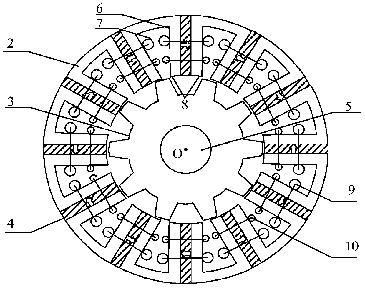
[0027] see figure 2 The motor body module 1 includes a stator 2 , a rotor 3 , a permanent magnet 4 , a rotating shaft 5 , a torque winding 9 , and a suspension force winding 10 , and the stator 2 includes stator teeth 6 , stator slots 7 and a stator yoke 8 . Stator 2 and rotor 3 adopt a double salient pole structure. The stator 2 is divided into 12 slots, and the rotor 3 is divided into 10 poles. It is made of M16_21G sil...


PUM


Abstract

The invention discloses a bearing-free magnetic flux switching permanent magnet motor rotor eccentric displacement compensation controller. A real-time rotating speed is input into an adaptive LMS filter, and the output of the adaptive LMS filter is a displacement compensation value; a rotor radial eccentric displacement and a rotor displacement command value and a displacement compensation valueare subjected to error comparison, and an error value is input into a corresponding PID controller; the PID controller converts the error value into two control components of the suspension force andinputs the suspension force into a suspension force winding current calculation module; a three-phase torque winding control current and a three-phase torque winding phase voltage are input into a torque winding air gap magnetic field estimation module, and the torque winding air gap magnetic field estimation module obtains rotor winding air gap flux linkage amplitude and phase and inputs the rotor winding air gap flux linkage amplitude and phase into the suspension force winding current calculation module; the suspension force winding current calculation module obtains a suspension force winding control current command value, and an inverter performs compensation control on the eccentric displacement of the suspension force rotor; the actual eccentric position center of the rotor does notneed to be detected, and the detection precision is improved.

Description

technical field [0001] The invention relates to a controller design for vector compensation control of rotor eccentric displacement of a bearingless flux switching permanent magnet motor to achieve stable suspension and high-speed operation. It is suitable for high performance control of a bearingless flux switching motor and is used in Chemical industry, aerospace, life science, semiconductor industry, electric vehicle, flywheel energy storage and other fields. Background technique [0002] The bearingless flux switching permanent magnet motor is a kind of magnetic bearing that not only inherits the characteristics of no mechanical friction, no lubrication, long service life, etc., but also has the advantages of simple rotor structure, high torque density and good heat dissipation conditions of the flux switching motor. Features make this motor suitable for high-speed and high-precision applications. In order to make the motor obtain stable suspension and high-speed rotati...

Claims


Application Information

Patent Timeline
Patent Type & Authority Applications(China)
IPC IPC(8): H02P21/14H02P25/026H02P27/08H02N15/00H02K21/28
CPCH02K21/28H02N15/00H02P21/14H02P25/026H02P27/08
Inventor 许颖朱熀秋吴熙计宗佑许波孙玉坤
Owner JIANGSU UNIV
Why Eureka
Try Eureka