Pressure composite sieve for pulping industry

An industry-leading and high-pressure technology, applied in the field of papermaking equipment, can solve the problems of high power consumption of compound screens, and achieve the effects of increasing pulping capacity, reducing equipment costs, and shortening conveying distances

Pending Publication Date: 2019-11-05
SHANDONG CHENZHONG MACHINERY
View PDF0 Cites 0 Cited by
  • Summary
  • Abstract
  • Description
  • Claims
  • Application Information

AI Technical Summary

Problems solved by technology

[0005] For this reason, an object of the present invention is to propose a kind of pressure composite screen for

Method used


Image

  • Pressure composite sieve for pulping industry
  • Pressure composite sieve for pulping industry
  • Pressure composite sieve for pulping industry

Examples


Embodiment Construction

[0030] Embodiments of the present invention are described in detail below, examples of which are shown in the drawings, wherein the same or similar reference numerals designate the same or similar elements or elements having the same or similar functions throughout. The embodiments described below by referring to the figures are exemplary and are intended to explain the present invention and should not be construed as limiting the present invention.

[0031] In describing the present invention, it is to be understood that the terms "upper", "lower", "front", "rear", "left", "right", "vertical", "horizontal", "top", The orientation or positional relationship indicated by "bottom", "inner", "outer", etc. is based on the orientation or positional relationship shown in the drawings, and is only for the convenience of describing the present invention and simplifying the description, rather than indicating or implying the referred device or positional relationship. Elements must hav...


PUM

PropertyMeasurementUnit
Thicknessaaaaaaaaaa

Abstract

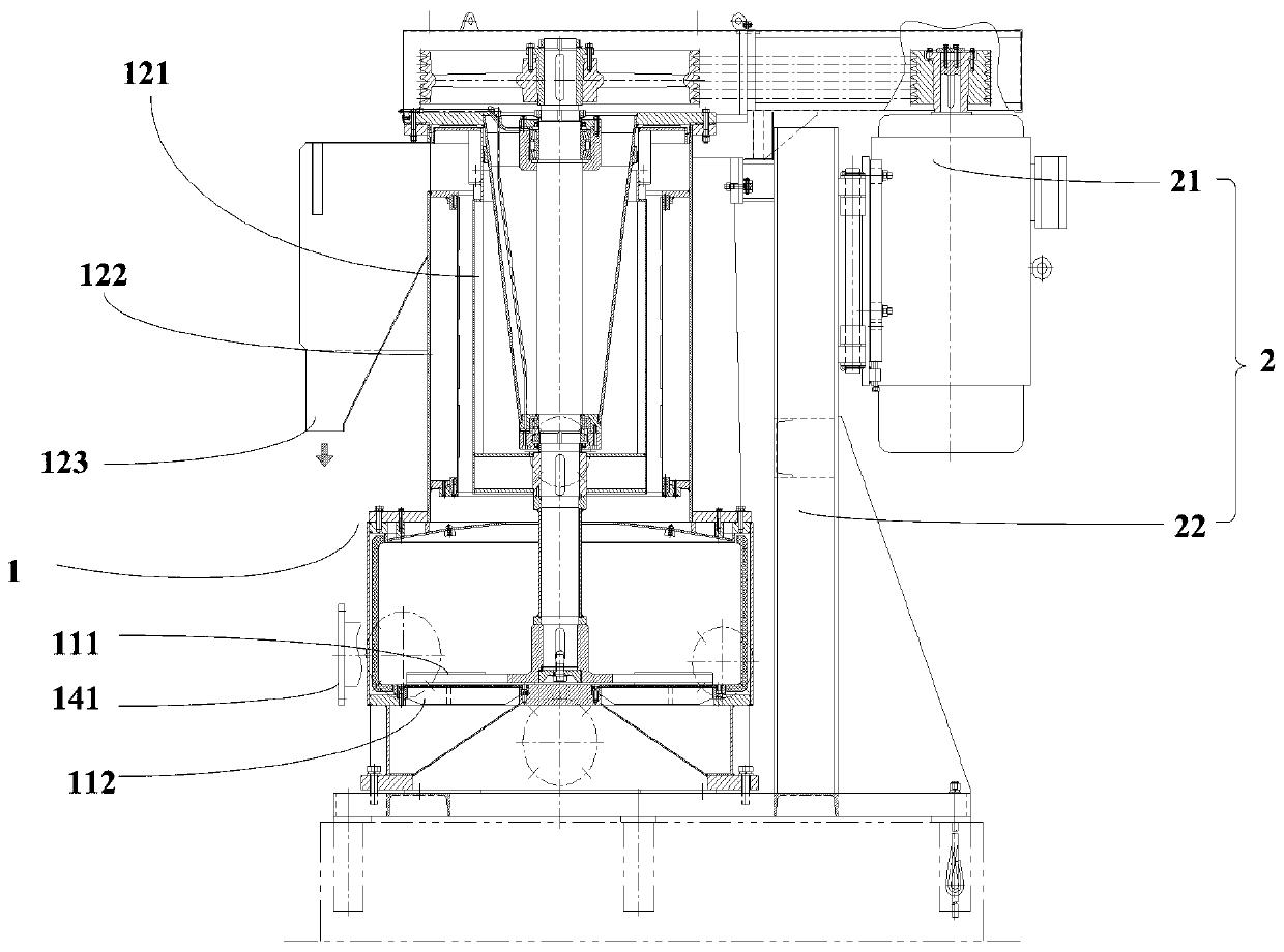
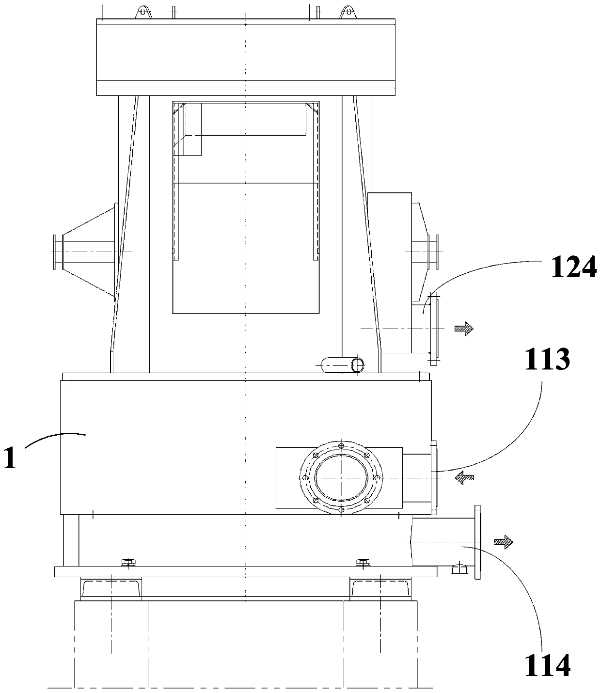
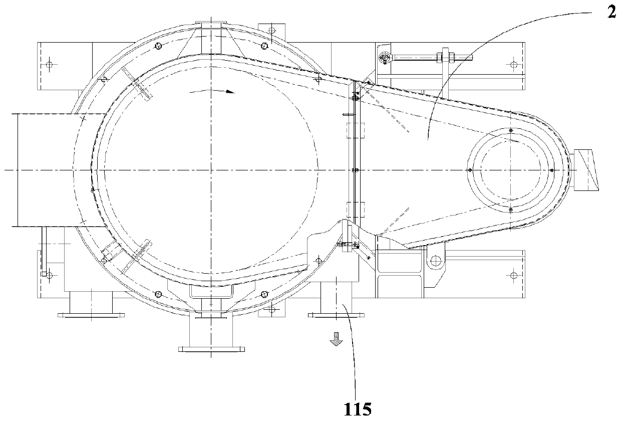
The invention relates to a pressure composite sieve for the pulping industry. The pressure composite sieve comprises a housing and a power device. The housing is internally provided with a pulp feeding and crushing zone and a washing and dewatering zone from bottom to top in sequence, wherein the pulp feeding and crushing zone is communicated with the washing and dewatering zone; the pulp feedingand crushing zone is provided with a crushing structure formed by an impeller and a sieve plate; the washing and dewatering area is internally provided with a washing and dewatering structure formed by a rotor and a sieve drum, and the rotor and the impeller are coaxially arranged in a vertical direction; the portion, corresponding to the pulp feeding and crushing zone, of the housing is providedwith a pulp inlet, a first good pulp outlet and a heavy slag outlet; the portion, corresponding to the washing and dewatering zone, of the housing is sequentially provided with a light slag outlet anda second good pulp outlet from top to bottom. The power device is fixed to one side of the top of the housing, an output end of the power device is provided with a first belt pulley, and transmissionthrough a belt and power transmission through a second belt pulley which is arranged on the top of a main shaft are realized; the pulp facing surface of each blade of the impeller is in a circular arc shape, and the length of the upper end surface of the end, away from an impeller core, of each blade is greater than that of the lower end surface of the end, away from the impeller core, of the blade, so that an included angle alpha is formed between the upper end surface and lower end surface of each blade.

Description

technical field [0001] The invention relates to the technical field of papermaking devices, in particular to a pressure composite screen used in the pulping industry. Background technique [0002] The coarse screen is used before the fine screen or front screen system of the pulping and papermaking production line. Its main function is to remove large heavy impurities, light impurities and coarse fibers in mechanical pulp, chemical pulp or waste paper pulp. The conventional pulping production process is to transport the tailings produced by the coarse screen to the slag separator for separation of fibers and impurities. The slag discharge separator only plays the role of separation and has no crushing function. The impurities separated by the slagging separator contain non-fragile pulp, which is re-transported back to the hydropulper for crushing, which makes the pulping process more cumbersome and increases the conveying equipment and pipelines. In order to solve the above...

Claims


Application Information

Patent Timeline
IPC IPC(8): D21B1/34D21D5/06
CPCD21B1/345D21D5/06
Inventor 李克雷王泽刚汪会秋荆强宋振建周善亮牟相忠庞同国崔利胜朱文芝
Owner SHANDONG CHENZHONG MACHINERY
Why Eureka
Try Eureka