Piezoelectric Drive Mutual Shield Electrode Miniature Electric Field Sensor

A technology of electric field sensor and driving electrode, which is applied in the direction of electrostatic field measurement, etc., can solve the problems that the electrode cannot be guaranteed to work in a resonance state, it is difficult to integrate and mass produce, and the resolution and sensitivity are low, so as to avoid direct interference and easy to assemble , Improve the effect of induction efficiency

Active Publication Date: 2021-04-06
INST OF ELECTRONICS CHINESE ACAD OF SCI +1
View PDF6 Cites 0 Cited by
  • Summary
  • Abstract
  • Description
  • Claims
  • Application Information

AI Technical Summary

Problems solved by technology

[0004] For the existing piezoelectric-driven miniature electric field sensors, Gong Chao et al. proposed an interlaced vibrating miniature electric field sensor, which connects the piezoelectric-driven ceramics to the sensing electrodes by gluing. The process precision is low, and it is not easy to integrate and mass-produce. low signal to noise ratio
Feng Ke et al. proposed a piezoelectric cantilever beam microsensor. The driving structure of the sensor is located directly below the sensing structure, and the noise coupling is large; and each sensing electrode of the sensor is independent of each other, so each sensing electrode has its own resonant frequency. It is impossible to ensure that all electrodes work in a resonance state, and the resolution and sensitivity are low

Method used


Image

  • Piezoelectric Drive Mutual Shield Electrode Miniature Electric Field Sensor
  • Piezoelectric Drive Mutual Shield Electrode Miniature Electric Field Sensor
  • Piezoelectric Drive Mutual Shield Electrode Miniature Electric Field Sensor

Examples


Embodiment 1

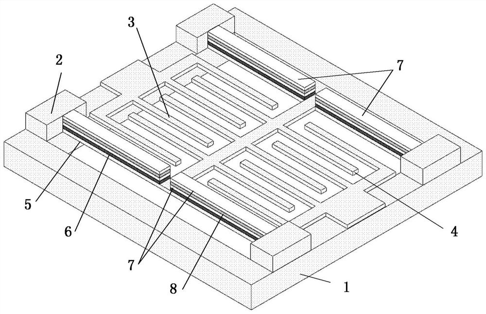
[0053] Embodiment 1 introduces a structural example of a piezoelectrically driven mutual shielding electrode miniature electric field sensor using strip-shaped sensing electrodes.

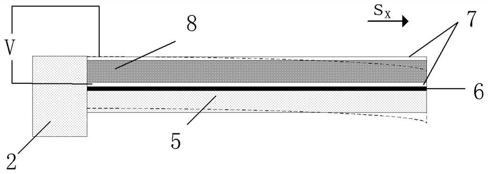
[0054] figure 1 It is a schematic structural diagram of a piezoelectrically driven mutual shield electrode miniature electric field sensor shown in Embodiment 1 of the present invention. refer to figure 1 As shown, in this embodiment, the piezoelectrically driven mutual shield electrode miniature electric field sensor includes: a substrate 1, a pillar 2, a fixed electrode 3, a movable electrode 4, an elastic beam 5, an insulating layer 6 and a driving structure.

[0055] In this embodiment, the movable electrodes 4 are arranged in two groups, and the fixed electrodes 3 are arranged in two groups; the pillars 2 are arranged in six groups, fixed on the substrate 1, for supporting and connecting the fixed electrodes 3 and the substrate 1, and elastic beams 5 and the substrate 1; the movable electrod...

Embodiment 2

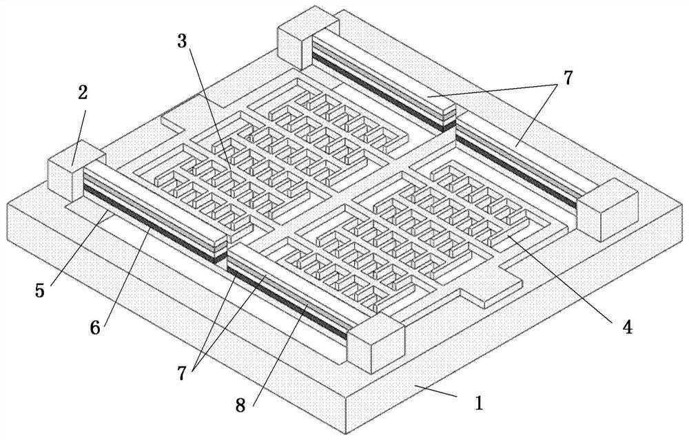
[0060] Embodiment 2 introduces a structural example of a piezoelectrically driven mutual shielding electrode miniature electric field sensor using comb-teeth sensing electrodes.

[0061] image 3 It is a structural schematic diagram of a piezoelectrically driven mutual shield electrode miniature electric field sensor shown in Embodiment 2 of the present invention. refer to image 3 As shown, the working principle of this embodiment 2 is consistent with that of embodiment 1. The piezoelectrically driven mutual shielding electrode miniature electric field sensor includes two sets of fixed electrodes 3 and two sets of movable electrodes 4; but the difference lies in: this embodiment Among them, the fixed electrodes 3 and the movable electrodes 4 are intersected by a comb structure.

Embodiment 3

[0063] Embodiment 3 introduces a structural example of a piezoelectrically driven miniature electric field sensor with mutually shielding electrodes using a serpentine composite elastic beam.

[0064] image 3 It is a structural schematic diagram of a piezoelectrically driven mutual shield electrode miniature electric field sensor shown in Embodiment 3 of the present invention. refer to Figure 4 As shown, the working principle of Embodiment 3 is consistent with that of Embodiment 1. The piezoelectrically driven mutual shielding electrode miniature electric field sensor includes two groups of fixed electrodes 3 and two groups of movable electrodes 4; the pillars are set to four groups; the driving structure is two group, located above the plane where the movable electrode 4 is located through the insulating layer 6 .

[0065] In this embodiment, the fixed electrodes 3 and the movable electrodes 4 are strip-shaped structures, arranged crosswise in the same plane; the elastic ...


PUM


Abstract

A piezoelectrically driven mutual shielding electrode miniature electric field sensor mainly includes: a substrate, a fixed electrode, a movable electrode, a pillar, an elastic beam, an insulating layer, and a driving structure; wherein, the movable electrode and the fixed electrode constituting the sensitive structure of the sensor are in the In the static state, they are located on the same plane, and both are sensing electrodes and mutually shielding electrodes; the driving structure composed of the driving electrode and the piezoelectric layer drives the movable electrode to move, so that the relative position of the fixed electrode and the movable electrode changes; the driving structure Located outside the sensing electrodes, the driving signal has little interference with signals on the sensing electrodes. The electric field sensor of the present invention can realize low-voltage driving, which is beneficial to reduce coupling interference and improve the signal-to-noise ratio of the sensor; through the arrangement of mutual shielding electrodes, the induction efficiency of the sensitive structure can be improved, and the resolution and sensitivity of the sensor can be improved; It has the characteristics of miniaturization, simple structure, easy integration and mass production.

Description

technical field [0001] The invention relates to the fields of sensors and micro-electromechanical systems (MEMS), in particular to a piezoelectrically driven miniature electric field sensor with mutually shielding electrodes. Background technique [0002] Electric field measurement technology has applications in many fields, and the core device of electric field measurement is the electric field sensor. Electric field sensors are widely used in many fields such as aerospace, meteorology, electric power, petroleum and petrochemical, and industrial production. [0003] Electric field sensors are widely used, and various sensor systems for different occasions have been researched according to different application occasions. According to its working principle, electric field sensors can be divided into two categories: charge-inductive electric field sensors and fiber optic sensors. The traditional electromechanical electric field sensor was developed earlier, so its technolog...

Claims


Application Information

Patent Timeline
Patent Type & Authority Patents(China)
IPC IPC(8): G01R29/12
CPCG01R29/12
Inventor 夏善红雷虎成彭春荣
Owner INST OF ELECTRONICS CHINESE ACAD OF SCI
Why Eureka
Try Eureka