

Oil-containing sludge deoiling and dewatering apparatus and oil-containing sludge deoiling and dewatering method
A dehydration device and sludge technology, applied in water/sludge/sewage treatment, sludge treatment, pyrolysis treatment of sludge, etc., can solve the problem of unqualified sludge oil content index, difficult removal of oil and cement mixture, and operation High operating costs and other issues, to achieve the effect of reducing repeated processing, preventing leakage and pollution, and saving operating costs
- Summary
- Abstract
- Description
- Claims
- Application Information
AI Technical Summary
Problems solved by technology
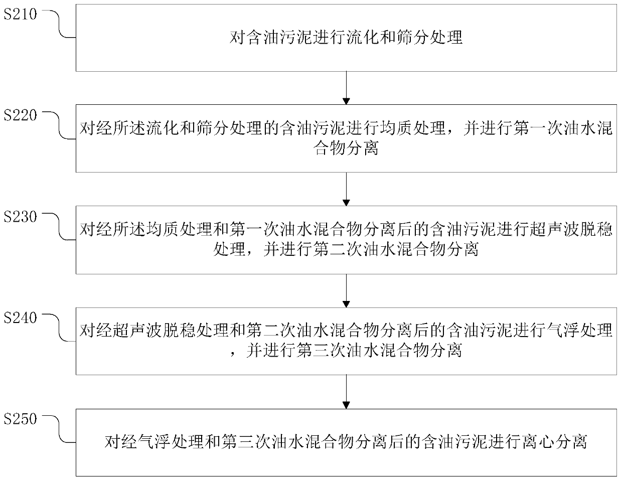
Method used
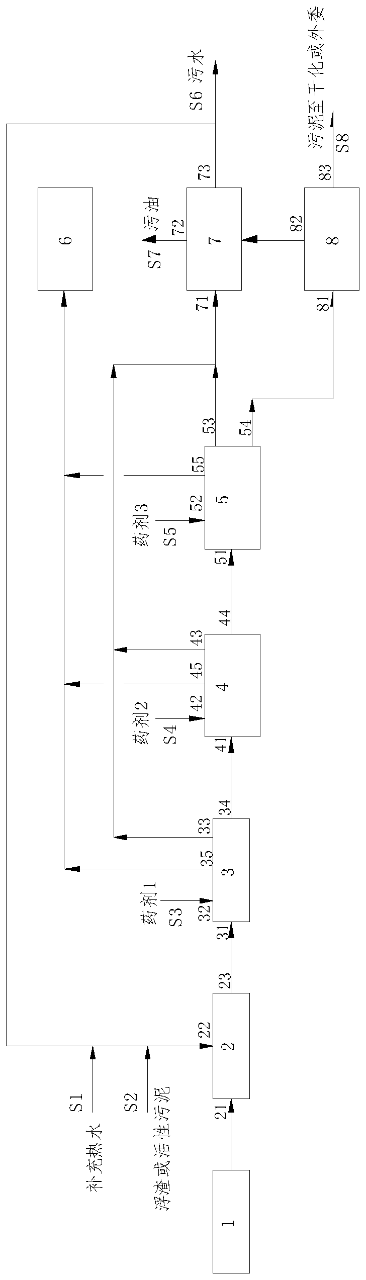
Image

Examples
Embodiment Construction
[0044] Example embodiments will now be described more fully with reference to the accompanying drawings. Example embodiments may, however, be embodied in many forms and should not be construed as limited to the embodiments set forth herein; rather, these embodiments are provided so that this application will be thorough and complete, and will fully convey the concept of example embodiments to those skilled in the art. The same reference numerals in the drawings denote the same or similar structures, and thus their detailed descriptions will be omitted.
[0045] Furthermore, the described features, structures, or characteristics may be combined in any suitable manner in one or more embodiments. In the following description, numerous specific details are provided in order to give a thorough understanding of embodiments of the invention. However, those skilled in the art will appreciate that the technical solutions of the present invention may be practiced without one or more o...
PUM
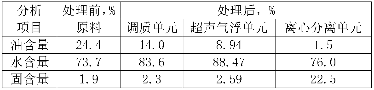
| Property | Measurement | Unit |
|---|---|---|
| oil removal rate | aaaaa | aaaaa |
| dehydration rate | aaaaa | aaaaa |
Abstract
Description
Claims
Application Information