High-spatial resolution photofilament fluorescence spectrum imaging and positioning method and system

A technology of fluorescence spectrum and positioning method, which is applied in spectrometry/spectrophotometry/monochromator, fluorescence/phosphorescence, radiation pyrometry, etc., which can solve the problem of monochromatic filament information and limited spatial resolution of filament imaging high-speed, high-spatial-resolution full-color filamentary spectral imaging and positioning, etc.

Active Publication Date: 2019-11-12
CHONGQING INST OF EAST CHINA NORMAL UNIV +2
View PDF3 Cites 3 Cited by
  • Summary
  • Abstract
  • Description
  • Claims
  • Application Information

AI Technical Summary

Problems solved by technology

However, the filament information obtained in this way is monochromatic, that is, there is only information about the intensity distribution of the filament, and does not include the spectral information of a specific position.
CCD pixels limit the spatial resolution of filament imaging (usually on the order of hundreds of microns); its frame speed limits the imaging rate (usually on the order of kilohertz)
Therefore, this method cannot achieve fast, high-spatial-resolution full-color filamentary imaging and localization
[0005] To sum up, although the measurement of fluorescence spectrum generated by laser filamentation provides new research and measurement methods for the fields of spectral remote sensing and nonlinear photophysics, the technology is still limited in terms of high spatial resolution positioning spectrum measurement. There are few technical deficiencies and defects

Method used


Image

  • High-spatial resolution photofilament fluorescence spectrum imaging and positioning method and system
  • High-spatial resolution photofilament fluorescence spectrum imaging and positioning method and system
  • High-spatial resolution photofilament fluorescence spectrum imaging and positioning method and system

Examples


Embodiment 1

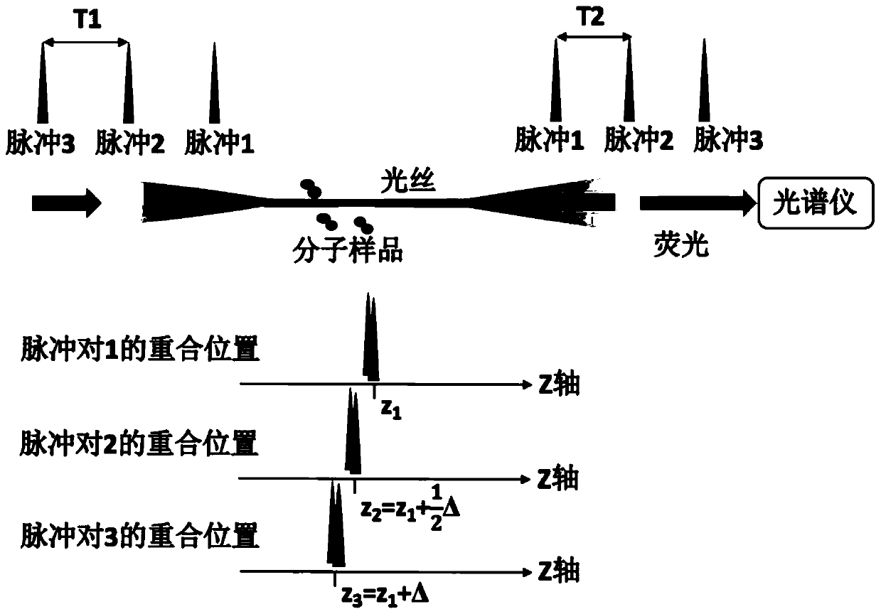
[0041] see figure 1 , using the above technology, the filament fluorescence spectrum imaging and positioning method of the present embodiment are as follows:

[0042]The method utilizes a group of two-color field asynchronous femtosecond pulses, which propagate collinearly and oppositely, and form a light filament in the medium (sample) after being focused by a lens. The two-color field pulses in the light filament interact nonlinearly at the coincident positions of time and space, and jointly excite the multiphoton absorption process of molecules, resulting in molecular fluorescence that can be measured by a spectrometer. Fluorescence is collected along the direction of propagation of one femtosecond light (i.e., the opposite direction of the other) and measured by a spectrometer. Since the femtosecond pulses propagating in opposite directions will meet at different positions of the light filament, the generated fluorescence has the position information of the light propagat...

Embodiment 2

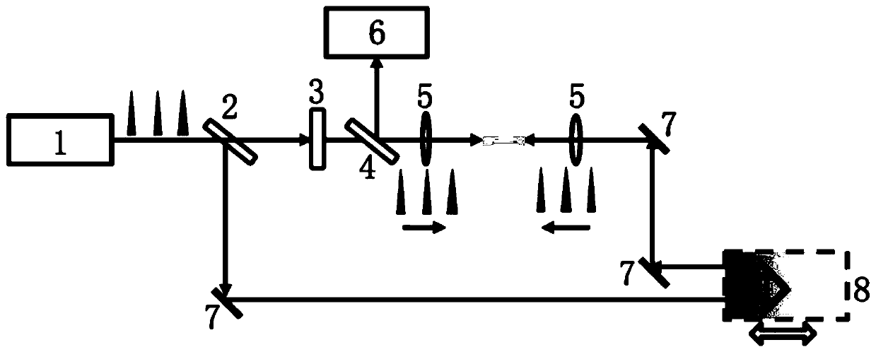
[0044] The above method can be implemented by using figure 2 In the system shown, a femtosecond pulsed laser 1 is used, and its laser parameters are as follows: output repetition frequency 1 kHz, pulse width 60 fs, center wavelength 800 nm, and single pulse energy 10 mJ. The near-infrared pulsed light is frequency-multiplied to generate ultraviolet (400nm) femtosecond pulses through a type I phase-matched frequency-doubling crystal. Femtosecond pulsed laser 1 outputs laser light through beam splitter 2 for beam splitting, in which the transmitted light passes through frequency doubling crystal 3 to obtain a beam in the 400nm band, and the reflected light part passes through mirror 7 and one-dimensional motor delay platform 8, and is then combined with frequency doubling Light travels collinearly. The two paths of light respectively pass through an ultraviolet fused silica plano-convex lens 5 with a focal length of f (=1000mm) to focus the light beams, and form light filament...

Embodiment 3

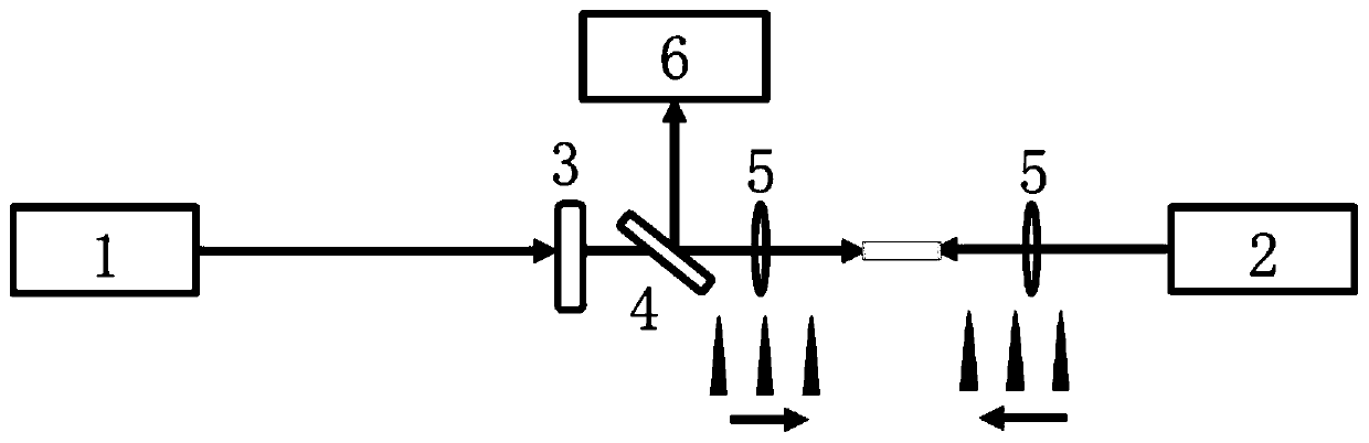
[0046] The above method can also be implemented by using image 3 In the system shown, the 800nm ​​fundamental frequency light passing through the one-dimensional motor delay platform is replaced by another femtosecond pulsed laser 1'. This laser has the same spectral parameters as the first one, but a different repetition rate or repetition period. Using the same optical path design as in Example 2 for the rest, the spatial and spectral information of the light filament can be obtained by means of non-mechanical scanning, thereby realizing fluorescence positioning and spectral measurement.

[0047] Specifically, a femtosecond laser 1 outputs laser light through a frequency doubling crystal 3 to obtain ultraviolet femtosecond pulses; another femtosecond laser 1' outputs laser light, which propagates oppositely and collinearly with the frequency doubling light; the two paths of light respectively pass through a focal length of The ultraviolet fused silica plano-convex lens 5 o...


PUM


Abstract

The invention provides a high-spatial resolution photofilament fluorescence spectrum imaging and positioning method and a system and relates to the field of ultrafast laser and laser spectrum measurement, in particular to ultrafast femtosecond optics, light-matter interaction physics and nonlinear spectroscopy. According to the high-spatial resolution photofilament fluorescence spectrum imaging and positioning method, opposite filamentation is carried out in a to-be-measured sample medium by using two-color laser field asynchronous femtosecond pulses; molecular fluorescence capable of being measured by a spectrometer is excited in common through nonlinear interaction of the two-color laser field asynchronous femtosecond pulses; and positioning and fixed-point analysis of a fluorescence spectrum are achieved through the self-scanning effect of the asynchronous pulses at the overlapping position along the light propagation axis. The method is a multidimensional spectrum measurement method, and high-precision spatial position information of ionized/dissociated molecules in a photofilament can be obtained while a femtosecond photofilament spectrum is measured.

Description

technical field [0001] The invention relates to the technical fields of ultrafast femtosecond optics, physics of interaction between light and matter, and nonlinear spectroscopy, in particular to the measurement technique of optical filament induced fluorescence spectroscopy. Background technique [0002] Femtosecond laser filamentation (referred to as optical filament) means that when the Kerr self-focusing and plasma defocusing generated during the propagation of ultrashort laser pulses reach a dynamic balance, a stable plasma channel can be formed in the medium. Filament-induced fluorescence spectroscopy means that the light intensity in the filament is clamped at 10 13 W / cm 2 On the order of magnitude, its intensity is sufficient to ionize or dissociate molecules in the atmospheric environment and keep them in an excited state; at the same time, the recombination process of free electrons and ions in the plasma channel will radiate a fluorescent fingerprint spectrum tha...

Claims


Application Information

Patent Timeline
Patent Type & Authority Applications(China)
IPC IPC(8): G01J3/28G01J3/44G01N21/64
CPCG01J3/2823G01J3/4406G01N21/6456G01N2021/6423
Inventor 曾和平闫明王小月
Owner CHONGQING INST OF EAST CHINA NORMAL UNIV
Why Eureka
Try Eureka