Downdraft carbon-gas co-production gasifier

A gasifier, downdraft technology, applied in gasification process, fixed bed gasification, gasification device details, etc., can solve the problem of uneven combustion of biomass fuel, inability to produce biomass carbon at the same time, and reliable ash discharge mechanism It can solve the problems of low sexuality, and achieve the effect of highlighting the substantive characteristics, improving the efficiency of gas production, and promoting the value of large

Pending Publication Date: 2019-11-15
周勇
View PDF0 Cites 10 Cited by
  • Summary
  • Abstract
  • Description
  • Claims
  • Application Information

AI Technical Summary

Problems solved by technology

However, there are still some deficiencies in the structure of feed and slag discharge: (1) The feed makes it difficult for wood chips with complex shapes to bridge the air, resulting in insufficient oxygen supply coverage, uneven combustion of biomass fuel, and insufficient gas production efficiency; ( 2) The reliability of the ash discharge mechanism is not high; (3) The system is too complicated and the equipment is too expensive
[0004] The main function of the technical solutions of the aforementioned patent applications is to convert biomass fuel into gas and realize the conversion of energy biomass. In the field of biomass energy utilization, comprehensive utilization of biomass is the most economically beneficial solution. Biomass carbon utilization Therefore, biomass carbon is an excellent by-product in the output of gasifier equipment. In the prior art, only biomass fuel is converted into gas, and biomass carbon cannot be produced at the same time, and the cogeneration of carbon and gas has not been solved. technical issues

Method used


Image

  • Downdraft carbon-gas co-production gasifier
  • Downdraft carbon-gas co-production gasifier
  • Downdraft carbon-gas co-production gasifier

Examples


Embodiment Construction

[0038] The present invention and its beneficial technical effects will be further described in detail below in conjunction with the accompanying drawings and preferred embodiments.

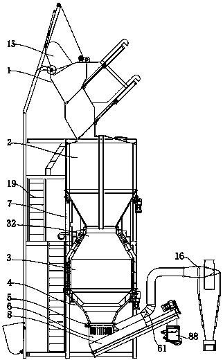
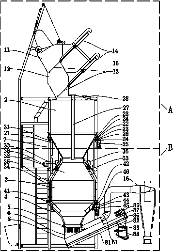
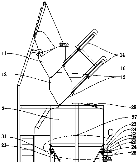
[0039] see Figure 1~Figure 2 , it can be seen from the figure that the downdraft carbon-gas cogeneration gasifier includes:

[0040] Furnace base 7, as the support of the entire downdraft carbon-gas cogeneration gasification furnace body;

[0041] The gasification reaction chamber 3 is arranged on the furnace base 7 as a place for gasification reaction of biomass fuel;

[0042] The feed bin 2 is arranged above the gasification reaction chamber 3 as a processing bin for biomass fuel;

[0043] The feed hopper 1 is arranged above the silo 2, and is used for loading biomass fuel and controlling the biomass fuel entering the silo 2;

[0044] The gasification blower 38 is arranged outside the gasification reaction chamber 4 to blow air for the gasification reaction chamber 3;

[0045] Wherein, the ...


PUM


Abstract

The invention discloses a downdraft carbon-gas co-production gasifier. The main structure of the gasifier comprises a feed hopper, a stock bin, a gasification reaction chamber, a double-section bucket-shaped water cooling sleeve, a turnover grate and a settling chamber from top to bottom; a carbon discharging auger is arranged at the bottom of the settling chamber; a bucket-shaped conical materialdrawing disc is arranged inside the lower part of the stock bin; and a bucket-shaped conical disc is stacked inside the upper part of the double-section bucket-shaped water cooling sleeve. Biomass fuel is firstly subjected to a high-temperature cracking gasification reaction in the gasification reaction chamber to generate fuel gas, and the fuel gas is discharged downwards from a fuel gas outletin the side wall of a settling chamber; and biomass fuel which is not completely reacted in the gasification reaction chamber is carbonized, then falls into the settling chamber and is cooled to formbiomass carbon, so that simultaneous co-production of carbon and gas of the biomass fuel is realized. The gasifier has the following characteristics: the structure is scientific and ingenious and thefeeding hopper with a double-layer structure can prevent gas from escaping during feeding; the bucket-shaped conical material drawing disc prevents the material bin from material bridging and arching;a gas supply pipe is used as a middle air inlet channel, so that gas feeding is more uniform without dead angles; and the turnover grate has a function of spraying water mist at the same time.

Description

technical field [0001] The invention relates to a gasification furnace, in particular to a gasification furnace using biomass as biomass fuel, straw, wood chips, garbage and other raw materials as biomass fuel. Background technique [0002] The gasification furnace is a gas preparation equipment that uses biomass as a biomass fuel. In order to solve the common problems of coking and excessive nitrogen oxides in pellet burners used in a large range of biomass-formed biomass fuels, the inventor invented The application number is 2016205519546, the name is "a biomass downdraft gasification and heating system", the application number is 2016205519550, the name is "a biomass gasification gas system and its ash discharge, slag and dust removal system"; the application No. 2016205519531 and a series of patents titled "A New Furnace Core Structure for Medium-to-Large Biomass Gasification Devices". However, there are still some deficiencies in the structure of feed and slag discharg...

Claims


Application Information

Patent Timeline
Patent Type & Authority Applications(China)
IPC IPC(8): C10J3/20C10J3/30C10J3/32C10J3/34C10J3/42C10J3/72C10J3/74C10J3/76C10J3/84
CPCC10J3/20C10J3/30C10J3/32C10J3/34C10J3/42C10J3/72C10J3/74C10J3/76C10J3/84C10J2200/152C10J2300/0916Y02P20/145
Inventor 周勇
Owner 周勇
Why Eureka
Try Eureka