Mass transfer enhancement type CO2 electroreduction electrolysis tank

A technology of CO2 and electrolytic cells, applied in electrolytic process, electrolytic components, electrolytic organic production, etc., can solve problems such as inability to run stably for a long time and affect the stability of product yield, so as to reduce the speed of attenuation and increase the degree of reaction , the effect of increasing the flow path

Pending Publication Date: 2019-11-15
GLOBAL ENERGY INTERCONNECTION RES INST CO LTD +2
View PDF0 Cites 11 Cited by
  • Summary
  • Abstract
  • Description
  • Claims
  • Application Information

AI Technical Summary

Problems solved by technology

[0005] In order to overcome the problem that the membrane electrode configuration electrolytic cell in the prior art cannot run stably for a long time during the electroreduction of carbon dioxide and affects the stability of the product yield, the present invention proposes a mass transfer enhanced CO2 electroreduction electrolytic cell

Method used


Image

  • Mass transfer enhancement type CO2 electroreduction electrolysis tank
  • Mass transfer enhancement type CO2 electroreduction electrolysis tank
  • Mass transfer enhancement type CO2 electroreduction electrolysis tank

Examples


Embodiment 1

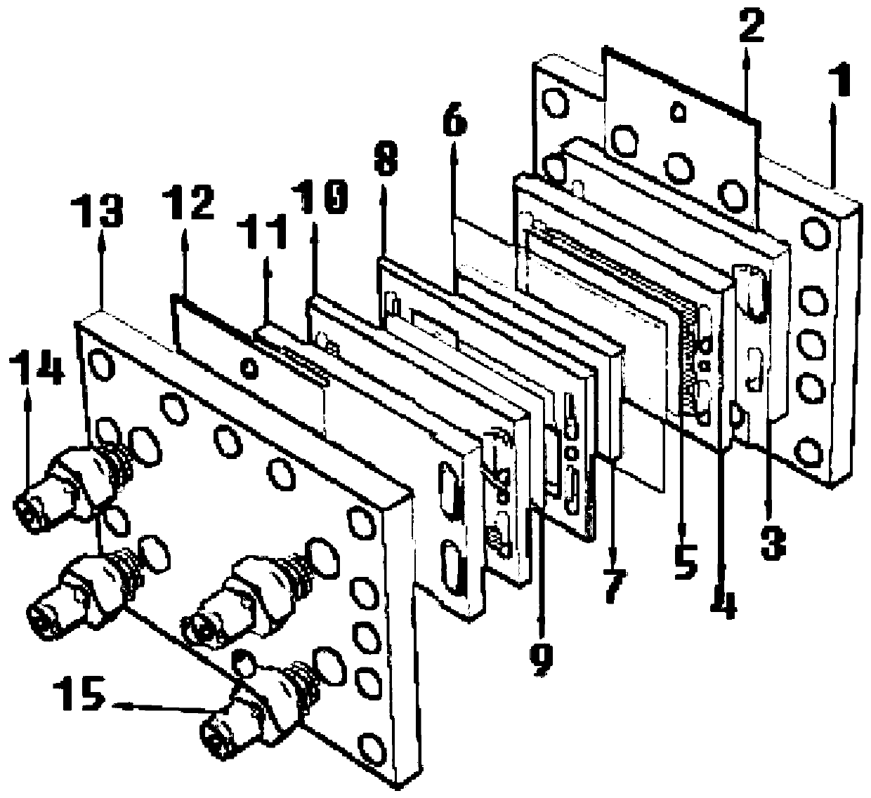
[0058] This embodiment provides an electrolytic cell for electroreducing carbon dioxide, such as figure 1 As shown, it includes a cathode assembly, an anode assembly and a diaphragm 6 that separates the two, and the diaphragm 6 is specifically an ion exchange membrane, more specifically a perfluorosulfonic acid proton exchange membrane (Nafion membrane); the cathode assembly has an electrolyte support layer connected in sequence 7. Solution flow field plate 8, cathode gas diffusion electrode 9, cathode flow field plate 10, cathode fluid distribution plate 11, cathode current collecting plate 12 and cathode end plate 13; The flow plate 2 , the anode fluid distribution plate 3 , the anode flow field plate 4 and the anode electrode plate 5 ; the diaphragm 6 is arranged between the electrolyte support layer 7 and the anode electrode plate 5 .

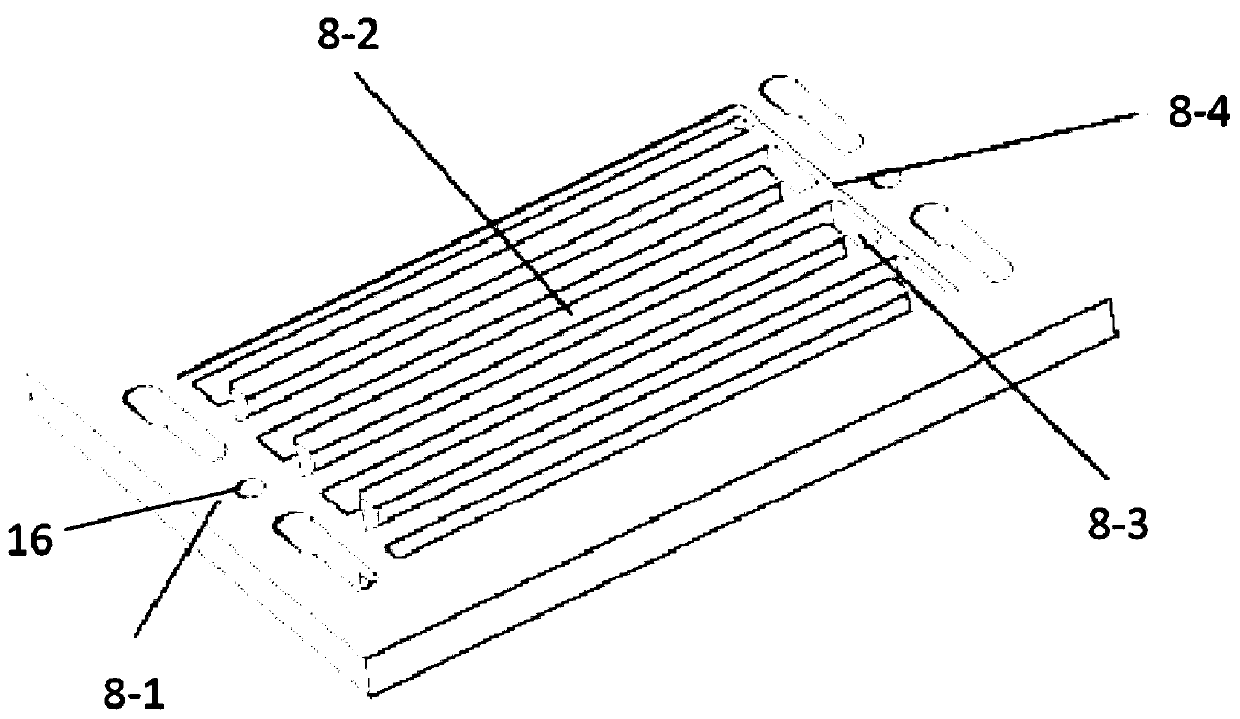
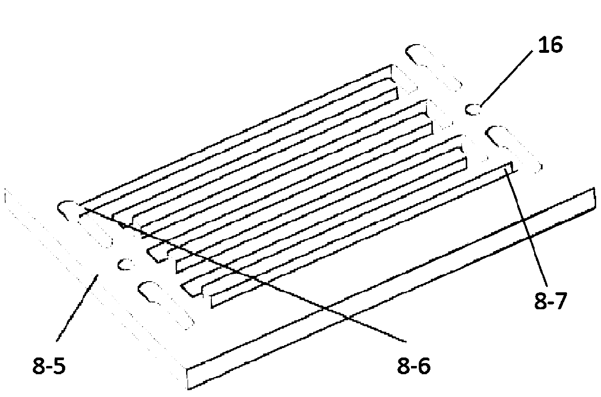
[0059] Such as Figure 2-3 As shown, the solution flow field plate 8 includes a first insulating surface 8-1 and a second insulating surf...

Embodiment 2

[0074] In order to verify the electrolytic cell for electroreduction of carbon dioxide with a unique structure of the present invention, a solution flow field plate with a thickness of 5 mm was selected to explore the influence of electrolyte flow rate on the performance and stability of carbon dioxide electroreduction. Among them, the electrolyte is potassium bicarbonate aqueous solution, the concentration of the electrolyte is 0.5mol / L, the operating temperature of the system is 25°C, and the working voltage is 0V~-10V. The structure of the electrolytic cell used in this embodiment is consistent with that of Embodiment 1. The corresponding test results are as Figure 6-Figure 7 shown.

[0075] from Image 6 It can be seen that when the battery voltage is -6.5V, when the electrolyte flow rate increases from 0ml / min to 4ml / min, the current density also increases from -8.90mA / cm 2 Boost to -33.38mA / cm 2 , indicating that the flow of electrolyte can significantly enhance the...

Embodiment 3

[0078] In order to verify the electrolytic cell for electroreduction of carbon dioxide with the unique structure of the present invention, a solution flow field plate with a thickness of 2 mm was selected to explore the influence of electrolyte flow rate on the performance and stability of carbon dioxide electroreduction. Among them, the electrolyte is potassium bicarbonate aqueous solution, the concentration of the electrolyte is 0.5mol / L, the operating temperature of the system is 25°C, and the working voltage is 0V~-10V. The structure of the electrolytic cell used in this embodiment is consistent with that of Embodiment 1. The corresponding test results are as Figure 8-Figure 9 shown.

[0079] from Figure 8 It can be seen that when the battery voltage is -10V, when the electrolyte flow rate increases from 1ml / min to 4ml / min, the current density also increases from -16.14mA / cm 2 Boost to -59.36mA / cm 2 , indicating that the flow of electrolyte can significantly enhance ...


PUM

PropertyMeasurementUnit
thicknessaaaaaaaaaa

Abstract

The invention discloses a CO2 electroreduction electrolysis tank. A solution flow field plate in the electrolysis tank is provided with flow channels penetrating through a first insulating surface anda second insulating surface, and the flow channels cooperate with a cathode gas diffusion electrode and an electrolyte supporting layer to form an electrolyte cavity for a reaction of CO2 with an electrolyte. The first insulating surface of the solution flow field plate is provided with a groove, and the electrolyte supporting layer is embedded in the groove to make the solution flow field platein close fit with the electrolyte supporting layer. A feeding groove communicated with the electrolyte cavity is arranged at one end of the electrolyte cavity, the feeding groove is communicated witha material channel, a discharge groove communicated with the electrolyte cavity is arranged at the opposite end of the electrolyte cavity, and the discharge groove is communicated with the material channel. The flow channels increase the flow paths of reactants in the electrolyte cavity, so the reaction degree of the reactants is increased, and the attenuation rate of the CO2 electrical reductionability is reduced, thereby the stability of the CO2 electrical reduction ability in the long-time reaction process is increased, and the stability of the product yield is ensured.

Description

technical field [0001] The invention belongs to the technical field of carbon dioxide electrochemistry and relates to a mass transfer enhanced CO 2 Electroreduction electrolytic cell. Background technique [0002] In recent years, with the development of the economy and the progress of the society, people have paid attention to carbon dioxide (CO 2 ) global climate and environmental issues caused by excessive emissions have been given a lot of attention. "Negative carbon economy" as a CO 2 The sustainable development model based on resource conversion is gradually being recognized and accepted by the society. However, CO 2 The chemical properties are stable, and it generally requires additional energy to activate and transform it. For this reason, in the actual industrial process, CO 2 There are not many cases of the resource conversion of natural gas, common chemical processes include urea synthesis, carbonate synthesis, methanol synthesis, methane CO 2 Restoration an...

Claims


Application Information

Patent Timeline
Patent Type & Authority Applications(China)
IPC IPC(8): C25B1/00C25B3/04C25B9/08C25B11/02C25B11/04C25B3/25C25B9/19
CPCC25B1/00C25B11/02C25B3/25C25B11/055C25B9/19
Inventor 杜兆龙徐桂芝宋鹏翔邓占锋李冰玉毛庆
Owner GLOBAL ENERGY INTERCONNECTION RES INST CO LTD
Why Eureka
Try Eureka