High resolution holographic microscope and method for living cell imaging

A live cell and microscope technology, applied in the field of high-resolution holographic microscope, can solve the problems of not making full use of the limited spatial bandwidth of the CCD camera, the system resolution is difficult to be further improved, and the distance between the sample and the recording surface is difficult to get close, etc. Achieve the effects of reducing the density of interference fringes, easy adjustment, and quantitative measurement

Active Publication Date: 2019-11-15
CHANGCHUN UNIV OF SCI & TECH
View PDF3 Cites 7 Cited by
  • Summary
  • Abstract
  • Description
  • Claims
  • Application Information

AI Technical Summary

Problems solved by technology

[0005] Also widely used in off-axis digital holographic microscopes, the optical path of the system has the disadvantages of complex structure, high coherence requirements of the light source, many rear-end optical components, and difficult adjustment; and the separation of object light and reference light increases the density of interference

Method used


Image

  • High resolution holographic microscope and method for living cell imaging
  • High resolution holographic microscope and method for living cell imaging
  • High resolution holographic microscope and method for living cell imaging

Examples


Embodiment 1

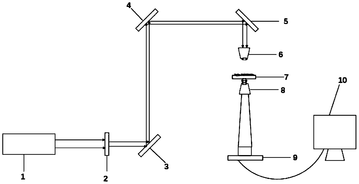
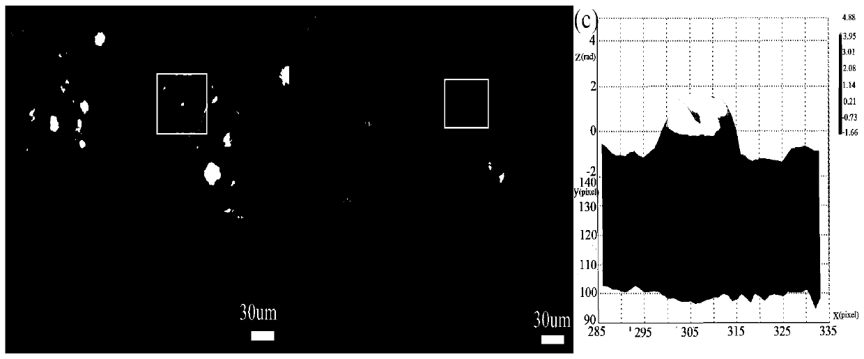
[0034] like image 3 for use figure 1 7721 live cell holograms and reconstructed images obtained by high-resolution holographic microscopy are shown. The laser 1 emits a coherent beam, and the power is continuously attenuated by the attenuator 2 to avoid damage to the living cell sample. The light source passes through three mirrors 3, 4, and 5 at an angle of 45° to the horizontal direction to change the direction of light propagation, so that the light The direction changes from horizontal to vertical, and is focused into a secondary point light source through the 10× microscope objective lens 6. When the secondary point light source passes through the three-dimensional micron displacement platform 7 loaded with 7721 living cell samples, the object light and the reference light interfere. A coaxial hologram is formed, and the image is enlarged by a 40× microscope objective lens 8, and finally received by a CCD camera 9 and stored in a computer 10, such as image 3 Shown in ...

Embodiment 2

[0036] like Figure 4 for use figure 1 Hacat live cell holograms and reconstructed images obtained by high-resolution holographic microscopy are shown. The laser 1 emits a coherent beam, and the power is continuously attenuated by the attenuator 2 to avoid damage to the living cell sample. The light source passes through three mirrors 3, 4, and 5 at an angle of 45° to the horizontal direction to change the direction of light propagation, so that the light The direction changes from horizontal to vertical, and is focused into a secondary point light source through the 10× microscope objective lens 6. When the secondary point light source passes through the displacement platform 7 carrying the Hacat living cell sample, the object light and the reference light interfere to form a coaxial light source. Hologram, the image is enlarged by 40 × microscope objective lens 8, finally received by CCD camera 9 and stored in computer 10, such as Figure 4 Shown in (a). Figure 4 (b) is ...


PUM

PropertyMeasurementUnit
Wavelengthaaaaaaaaaa
Coherence lengthaaaaaaaaaa

Abstract

The present invention discloses a high resolution holographic microscope and a method for living cell imaging, and belongs to the technical field of holographic microimaging. In a holographic opticalpath, when a secondary point light source passes through a living cell sample, diffracted object light interferes with undiffracted reference light to form an in-line hologram; the image is magnifiedby a high power microobjective, received by a CCD camera and stored in a computer; and a reconstructed image is obtained by computer numerical reconstruction. The invention uses a low power microobjective to convert a parallel light source into the secondary point light source combined with the object light and the reference light in the same direction during a recording process, makes full use ofa limited spatial bandwidth of the CCD camera, greatly improves the resolution of the holographic microscope system, uses a three-dimensional micron-scale displacement platform to precisely adjust the microscopic resolution and receives more interference outer ring fringes by shortening the recording distance, which includes high-frequency information of the sample playing a key role in reconstructing the image. Combined with the high power microobjective in front of the CCD camera, non-contact, non-invasive, fast, quantitative and high-resolution holographic microimaging of the living cell sample can be realized.

Description

technical field [0001] The invention relates to the technical field of holographic microscopic imaging, in particular to a high-resolution holographic microscope and method for living cell imaging. Background technique [0002] When a traditional optical microscope measures a sample, since the detector can only record the intensity information of the light wave of the object, it can only obtain the two-dimensional shape of the object. Electron microscopes and scanning probe microscopes require pretreatment of the sample to be tested before measurement, and the scanning process takes a certain amount of time, so it is impossible to perform non-contact, non-damaging, fast, and real-time measurement of the sample. The digital holographic microscopic imaging technology developed in recent years has the unique advantages of non-contact, non-destructive, fast, real-time and quantitative imaging of biological samples, which overcomes the limitations of traditional microscopic imagi...

Claims


Application Information

Patent Timeline
IPC IPC(8): G01N21/84G01N21/45G02B21/00G02B21/06G02B21/36G03H1/00
CPCG01N21/84G01N21/453G03H1/0005G02B21/0004G02B21/06G02B21/361G03H2001/005
Inventor 赵跇坤王作斌布莱斯曹亮董莉彤王璐曲英敏
Owner CHANGCHUN UNIV OF SCI & TECH
Why Eureka
Try Eureka