
Multi-working-condition magnetic flux leakage controllable wide-speed-regulation high-efficiency permanent magnet brushless motor

A permanent magnet brushless motor, controllable technology, applied to synchronous motors with static armatures and rotating magnets, magnetic circuit shape/pattern/structure, magnetic circuit, etc. speed and other issues to achieve the effect of improving utilization and increasing magnetic resistance

Inactive Publication Date: 2019-11-19
JIANGSU UNIV
View PDF10 Cites 15 Cited by
  • Summary
  • Abstract
  • Description
  • Claims
  • Application Information

AI Technical Summary

Problems solved by technology

[0005] The main content of the present invention is to solve the problems existing in the weak magnetic speed regulation of permanent magnet synchronous motors, and propose a multi-working condition magnetic leakage controllable wide speed regulation high-efficiency permanent magnet brushless motor for electric vehicles

Method used


Image

  • Multi-working-condition magnetic flux leakage controllable wide-speed-regulation high-efficiency permanent magnet brushless motor
  • Multi-working-condition magnetic flux leakage controllable wide-speed-regulation high-efficiency permanent magnet brushless motor
  • Multi-working-condition magnetic flux leakage controllable wide-speed-regulation high-efficiency permanent magnet brushless motor

Examples


Embodiment Construction

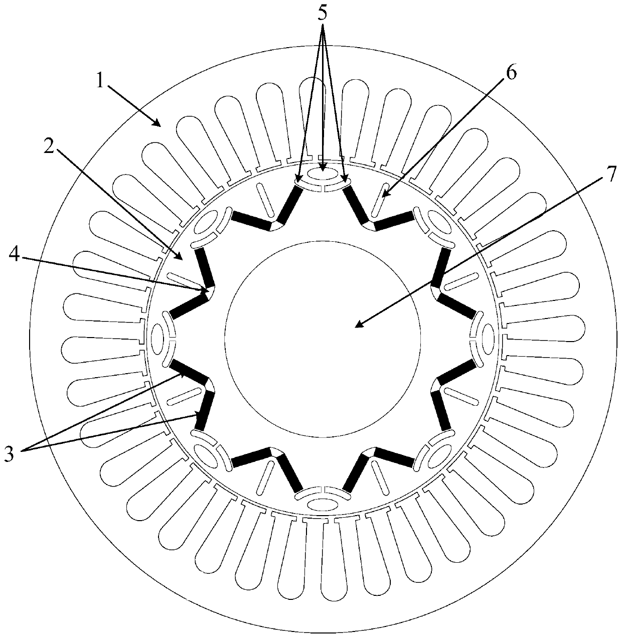
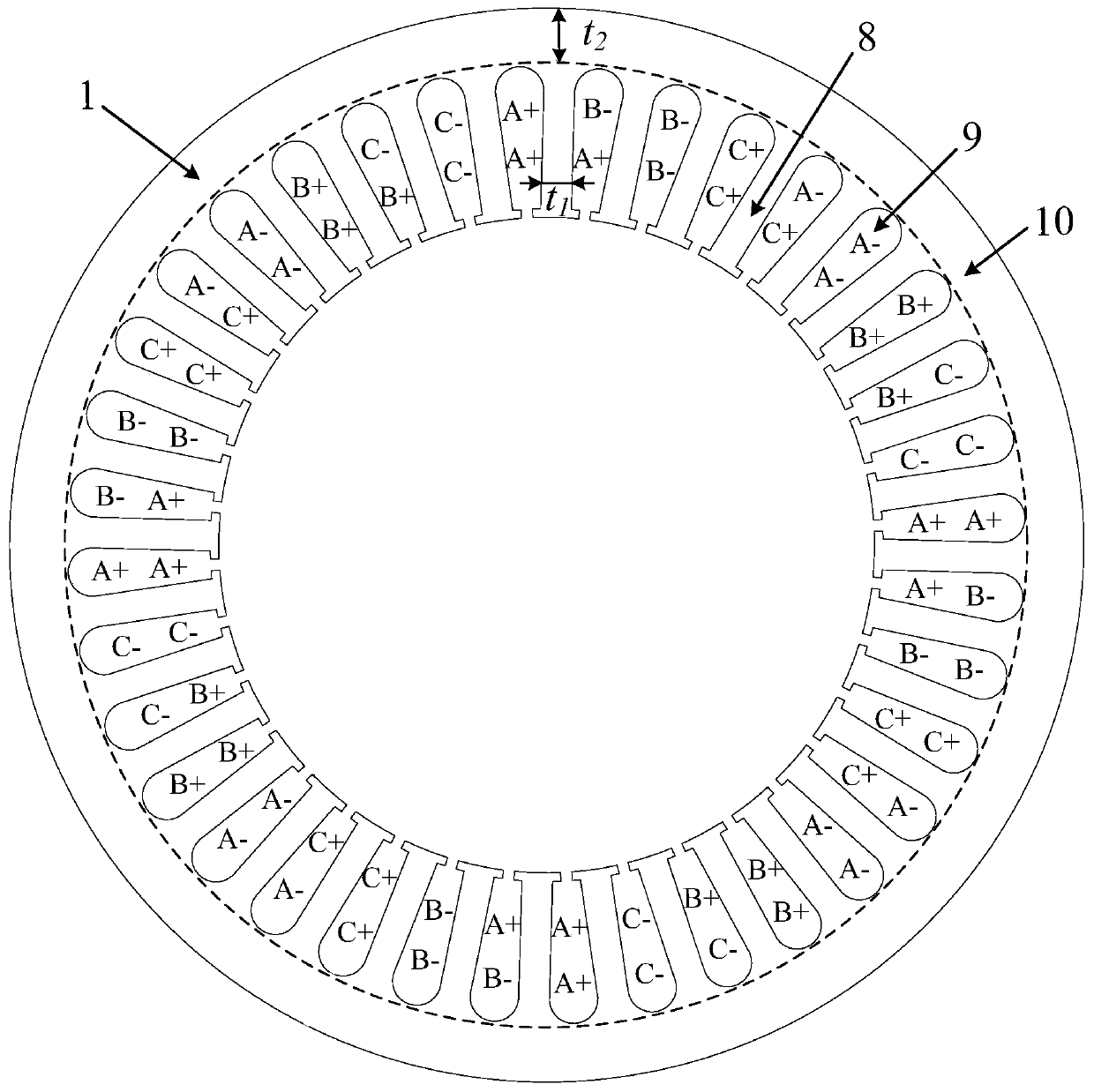
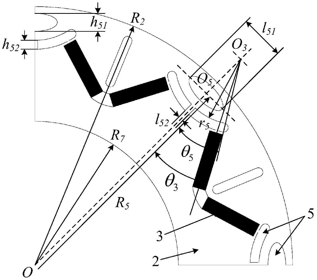
[0037] see figure 1 , figure 2 , the present invention comprises a stator 1, a rotor 2, a rotating shaft 7, 36 stator slots 9 evenly distributed in the circumferential direction of the stator 1, armature windings are arranged in the stator slots 9, the armature windings do not completely fill the stator slots 9, and the slot fullness rate is the same as The temperature rise of the motor winding is related to the design of the cooling system; there is an air gap between the inner wall of the stator 1 and the outer wall of the rotor 2, and the thickness of the air gap is related to the power level of the motor, the permanent magnet material, the processing and assembly process of the stator 1 and the rotor 2; the rotor 2 is connected with the rotating shaft 7 by a key and rotates concentrically. Both the stator 1 and the rotor 2 are made of laminated silicon steel sheets with a thickness of 0.35 mm, and the lamination coefficient is 0.95; the winding is made of enamelled coppe...


PUM

PropertyMeasurementUnit
Thicknessaaaaaaaaaa

Abstract

The invention discloses a multi-working-condition magnetic flux leakage controllable wide-speed-regulation high-efficiency permanent magnet brushless motor. The motor comprises a stator 1, a rotor 2 and a rotating shaft 7 which are sequentially arranged from outside to inside. The stator 1 is composed of stator teeth 8, stator grooves 9 and a stator yoke 10, the stator grooves 9 are formed betweenevery two adjacent stator teeth 8, the radial cross section of each stator tooth 8 is in a T shape, the top of each T shape is close to the rotor 2, and the bottom of each T shape is connected with the stator yoke 10 into a whole. Armature windings are arranged in the stator grooves 9, and the stator grooves 9 are not completely filled with the armature windings; an air gap is formed between theinner wall of the stator 1 and the outer wall of the rotor 2; the rotor 2 and the rotating shaft 7 are connected through a key and rotate concentrically. Because only the single excitation source is adopted, the advantage that the air-gap magnetic field is variable is achieved, no extra electric excitation winding needs to be added, no low-coercivity permanent magnet material capable of achievingon-line magnetism adjustment needs to be additionally introduced, the structure is simple and compact, manufacturing and machining are convenient, extra losses are avoided, and the efficiency of the motor can be better improved.

Description

technical field [0001] The invention belongs to the technical field of permanent magnet motor manufacturing, and relates to a built-in permanent magnet synchronous motor, in particular to a built-in permanent magnet synchronous motor with low saliency rate characteristics. Background technique [0002] In recent years, the contradictions between the rapid development of the global traditional fuel vehicle industry and oil shortages and environmental pollution have become increasingly prominent. With its remarkable advantages such as high efficiency and zero emission, electric vehicles have become one of the main directions for the development of new energy vehicles. At the same time, the complex driving environment and variable operating conditions of electric vehicles put forward more stringent performance requirements for the motor and its drive system. Permanent magnet synchronous motors have been widely used in electric vehicle electric drive systems due to their advant...

Claims


Application Information

Patent Timeline
IPC IPC(8): H02K21/16H02K1/14H02K1/16H02K3/02H02K3/34H02K1/27
CPCH02K1/146H02K1/165H02K1/2773H02K3/02H02K3/34H02K21/16H02K2213/03
Inventor 朱孝勇吴文叶葛凌昱进全力项子旋
Owner JIANGSU UNIV
Learn More