Reflective phase-orthogonal single-frequency laser interferometry device and measurement method

A single-frequency laser and reflective technology, applied in the direction of measuring device, phase influence characteristic measurement, optical device, etc., can solve the problem of changing the degree of signal distortion, the inability to complete nonlinear error compensation, and the inability to eliminate polarization leakage of polarization beam splitters, etc. problems, to achieve the effect of improving measurement accuracy and environmental noise

Active Publication Date: 2021-04-30
UNIV OF SHANGHAI FOR SCI & TECH
View PDF8 Cites 0 Cited by
  • Summary
  • Abstract
  • Description
  • Claims
  • Application Information

AI Technical Summary

Problems solved by technology

This method is suitable for applications where the measuring mirror has only a small stroke or is still. Otherwise, other angular motion errors introduced by the movement of the measuring mirror in actual measurement will change the degree of signal distortion, so that the complete compensation of nonlinear errors cannot be completed.
The patent application publication number CN106225667A suppresses polarization aliasing by inserting two polarization beam splitters with high extinction ratio in the optical path, thereby reducing the non-orthogonal error, and correcting the direct current by adjusting the gain of the photodetector in the receiving circuit Offset error and amplitude error, the whole system has a certain complexity, and the high extinction ratio polarizer can only suppress the polarization aliasing in the interference optical path, but cannot eliminate the polarization leakage of the two polarization beam splitters in the receiving optical path

Method used


Image

  • Reflective phase-orthogonal single-frequency laser interferometry device and measurement method
  • Reflective phase-orthogonal single-frequency laser interferometry device and measurement method
  • Reflective phase-orthogonal single-frequency laser interferometry device and measurement method

Examples


Embodiment Construction

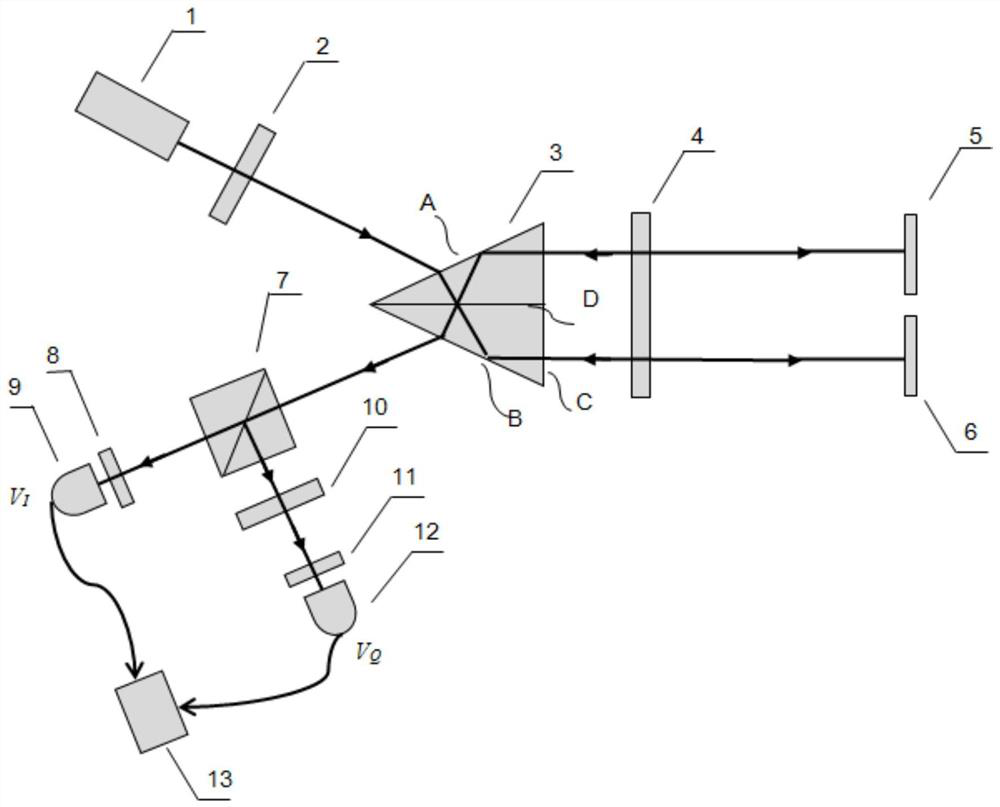
[0034]Such asfigure 1The reflective phase orthogonal single-frequency laser interference measuring device is an embodiment, and the present invention will be described in detail.

[0035]A high-precision reflective phase orthogonal single-frequency laser interference measuring device includes a single frequency laser source 1, a polarizer 2, a polarization spectroscopic prism 3, a first 1 / 4 wave plate 4, a reference mirror 5, measuring mirror 6, the semi-transparent branch prism 7, the first inspection mouser 8, the first photodetector 9, the second 1 / 4 wave plate 10, the second inspector 11, the second photodetector 12, interference signal processing Unit 13.

[0036]The polarization prism 3 can be bonded from a right angle prism at which the two structural sizes is identical, and the opposite side of the two right-angle prisms is surface A and the surface B, the second surface of the polarized spectroscopic prism 3 is surface C, at sticking The surface D is plated with a layer of polari...


PUM


Abstract

The invention relates to a reflective phase-orthogonal single-frequency laser interferometry device and measurement method. A single-frequency laser source provides linear 45° polarized light. The P light and S light exit in parallel in spatial position, pass through the 1 / 4 wave plate, project to the measurement plane mirror and the reference plane mirror respectively, return, pass through the 1 / 4 wave plate again, and combine the light through the polarization beam splitter to exit. The outgoing combined beam is evenly split by the half-transparent mirror, and the transmitted light is received by the photodetector after passing through the analyzer to generate an interference signal V I ; The reflected light passes through the quarter-wave plate and then the detector receives the signal from the photodetector to generate an interference signal V Q . Polarization beam splitters are used to form balanced reference light and measurement light with adjustable spatial distance, which greatly suppresses environmental noise and improves measurement accuracy; by adjusting the azimuth of the polarizer, it is used for nonlinear error correction in the signal processing stage to improve measurement precision.

Description

Technical field[0001]The present invention relates to an optical measuring device, and more particularly to a reflective phase orthogonal single-frequency laser interference measuring device and a measurement method.Background technique[0002]Whether it is single frequency or a difference, the double beam laser interferometer has been widely used in high-precision sensing applications and measurements. Compared with the dual-band laser interferometer, the single-frequency laser interferometer using the phase orthogonal method is simple, the signal processing is easy, the measurement speed is not limited, and the measurement beam amplitude and phase change can be obtained, so it Widely used in various measurement areas such as high-precision displacement measurements, face measurements and refractive index assays such as fluid, gas. However, in practical applications, the presence of single-frequency laser interferometer on sensitive and nonlinear errors of measuring environmental noi...

Claims


Application Information

Patent Timeline
Patent Type & Authority Patents(China)
IPC IPC(8): G01B9/02G01N21/45
CPCG01B9/0201G01B9/02012G01B9/02015G01B9/02057G01B9/02075G01N21/45
Inventor 乐燕芬金施嘉珞金涛
Owner UNIV OF SHANGHAI FOR SCI & TECH
Why Eureka
Try Eureka