Compound lens, and encodable single-frame imaging device and method

A compound lens and imaging device technology, which is applied to lenses, optics, instruments, etc., can solve the problems of diffraction efficiency and energy loss, limited working frequency bandwidth, reduced imaging field of view, etc., and achieves improved optical path stability, simple and fast recording. with reproduction, high-resolution effects

Active Publication Date: 2019-11-22
XIDIAN UNIV
View PDF4 Cites 1 Cited by
  • Summary
  • Abstract
  • Description
  • Claims
  • Application Information

AI Technical Summary

Problems solved by technology

However, the current pure phase-modulated SLM has problems of diffraction efficiency and energy loss, and the cost of the device is high, the operating frequency bandwidth is limited, and the filling factor is limite...

Method used


Image

  • Compound lens, and encodable single-frame imaging device and method
  • Compound lens, and encodable single-frame imaging device and method
  • Compound lens, and encodable single-frame imaging device and method

Examples


Embodiment 1

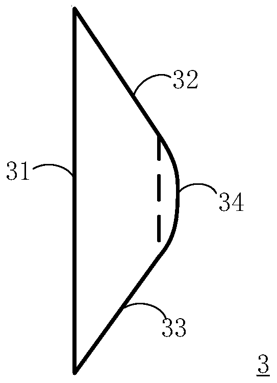
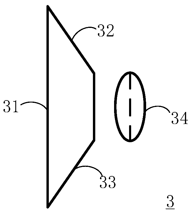
[0060] See figure 1 , figure 1 It is a schematic structural diagram of a compound lens provided by an embodiment of the present invention. The composite lens 3 is modified on the basis of a prism, and includes a parallel light incident surface 31 , a first plane wave exit surface 32 , a second plane wave exit surface 33 and a spherical wave exit surface 34 .

[0061] Among them, the spherical wave exit surface 34 is in the shape of a lens, preferably in the shape of a convex lens.

[0062] The parallel light incident surface 31 , the first plane wave exit surface 32 , and the second plane wave exit surface 33 are all planar. Parallel light incident surface 31 is arranged opposite to spherical wave exit surface 34, and the width of parallel light incident surface 31 is greater than the width of spherical wave exit surface 34, and the width of preferred parallel light incident surface 31 is 3 times of the width of spherical wave exit surface 34. times. The first plane wave e...

Embodiment 2

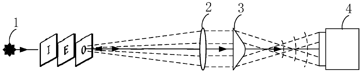
[0070] See image 3 , image 3 It is a schematic structural diagram of a Fresnel incoherent holography-based encodable single-frame imaging device provided by an embodiment of the present invention. The imaging device includes: a light source 1 , a collimator lens 2 , a composite lens 3 and an optical signal receiver 4 .

[0071] The light source 1 emits incoherent light. The objects O, E, and I are placed on the incoherent light path, and the objects O, E, and I receive the incoherent light and emit the outgoing light. The collimating lens 2 is arranged on the optical path of the outgoing light, and is used for adjusting the outgoing light to be parallel light or approximately parallel light.

[0072] Specifically, the light source 1 can directly illuminate the objects O, E, and I. For example, when the objects O, E, and I are transparent, the incoherent light from the light source 1 can pass through the objects O, E, and I. to propagate, such as image 3 shown. The lig...

Embodiment 3

[0080] On the basis of the second embodiment, this embodiment takes the composite lens 3 as an example of a processed isosceles trapezoidal prism to describe the relationship between the parameters of the composite lens 3 and the parameters of the optical signal receiver 4 .

[0081] See Figure 7 , Figure 7 It is a schematic diagram of parameters of a compound lens and an optical signal receiver provided by an embodiment of the present invention.

[0082] Figure 7 Among them, a is the upper base of the compound lens 3, that is, the width of the spherical wave exit surface 34, and b is the lower base of the compound lens 3, that is, the width of the parallel light incident surface 31, and a and b satisfy b=3a, and h is the compound lens The height of 3 (the distance from the bottom edge to the lowest point of the spherical wave exit surface), α is the angle at which the plane wave beam exits, n is the refractive index of the compound lens, n 0 =1 is the refractive index o...


PUM


Abstract

The invention relates to a compound lens, and an encodable single-frame imaging device and method. The compound lens comprises a parallel light incident surface, a first plane wave emergent surface, asecond plane wave emergent surface and a spherical wave emergent surface, and the spherical wave emergent surface is lens-shaped; the parallel light incident surface is opposite to the spherical waveemergent surface, and the width of the parallel light incident surface is greater than that of the spherical wave emergent surface; the first plane wave emergent surface is opposite to the second plane wave emergent surface; the spherical wave emergent surface is arranged between the first plane wave emergent surface and the second plane wave emergent surface. The composite lens can modulate incoherent parallel light into plane waves and spherical waves; the problems of energy loss, bandwidth limitation, efficiency and fill factor constraint, constraint of the size on the field of view and the like of a spatial light modulator are solved, the imaging advantages of Fresnel associated holography are reserved, incident light beams are completely modulated while the light path stability is improved, and single-frame Fresnel associated holography imaging with pure optical elements is achieved.

Description

technical field [0001] The invention belongs to the technical field of digital holographic imaging, and in particular relates to a composite lens, an encoding single-frame imaging device and an imaging method. Background technique [0002] Holography is a classic three-dimensional imaging technology, and holography is a brief summary of the essence of "all information". In 1948, Gabor founded holography, and obtained the first hologram and reconstructed image in human history for the first time in experiments. Holography has gone through more than 70 years of history in the continuous reform and development, and has a very important position in the field of information optics. It has been widely used in science and technology, industry, agriculture, medicine, art, cultural media, business and other fields. The recording and reproduction process of traditional holography requires coherent light illumination, which not only has extremely high requirements on the environment, ...

Claims


Application Information

Patent Timeline
IPC IPC(8): G02B3/02G03H1/06G03H1/04
CPCG02B3/02G03H1/0402G03H1/0443G03H1/06
Inventor 刘杰涛邵晓鹏计婷李伟孙雪莹张乐
Owner XIDIAN UNIV
Why Eureka
Try Eureka