Signal connection structure based on shape protection, assembling method thereof and packaging box body

A signal connection and signal connector technology, applied in the direction of connection/disconnection, connection, coupling device, etc. of the connection device, which can solve the damage of the connector package shell, the disconnection of the connector, and the deterioration of the connection strength between the connector and the circuit board, etc. problem, to achieve the effect of increasing connection strength, reducing tension, and reducing the possibility of light leakage

Pending Publication Date: 2019-11-22
UNIV OF SCI & TECH OF CHINA
View PDF0 Cites 0 Cited by
  • Summary
  • Abstract
  • Description
  • Claims
  • Application Information

AI Technical Summary

Problems solved by technology

[0004] The technical difficulty is that the connector that seems to be well connected to the box at room temperature, in an extremely low temperature environment, due to the different characteristics of the thermal expansion coefficient of the material, will cause the material to separate and cause light leakage (the leakage of a single photon is enough to make the quantum processor receives considerable noise), which seriously affects the operation of the quantum processor
On the other hand, due to the separation of materials caused by different thermal expansion coefficients of materials, it is easy to deteriorate the connection strength between the connector and the circuit board, and it is easy to detach during the plugging and unplugging process of the connector, resulting in damage to the connector and even the packaging shell.

Method used


Image

  • Signal connection structure based on shape protection, assembling method thereof and packaging box body
  • Signal connection structure based on shape protection, assembling method thereof and packaging box body
  • Signal connection structure based on shape protection, assembling method thereof and packaging box body

Examples


no. 1 example

[0040] In the first exemplary embodiment of the present disclosure, a signal connection structure based on shape protection is provided.

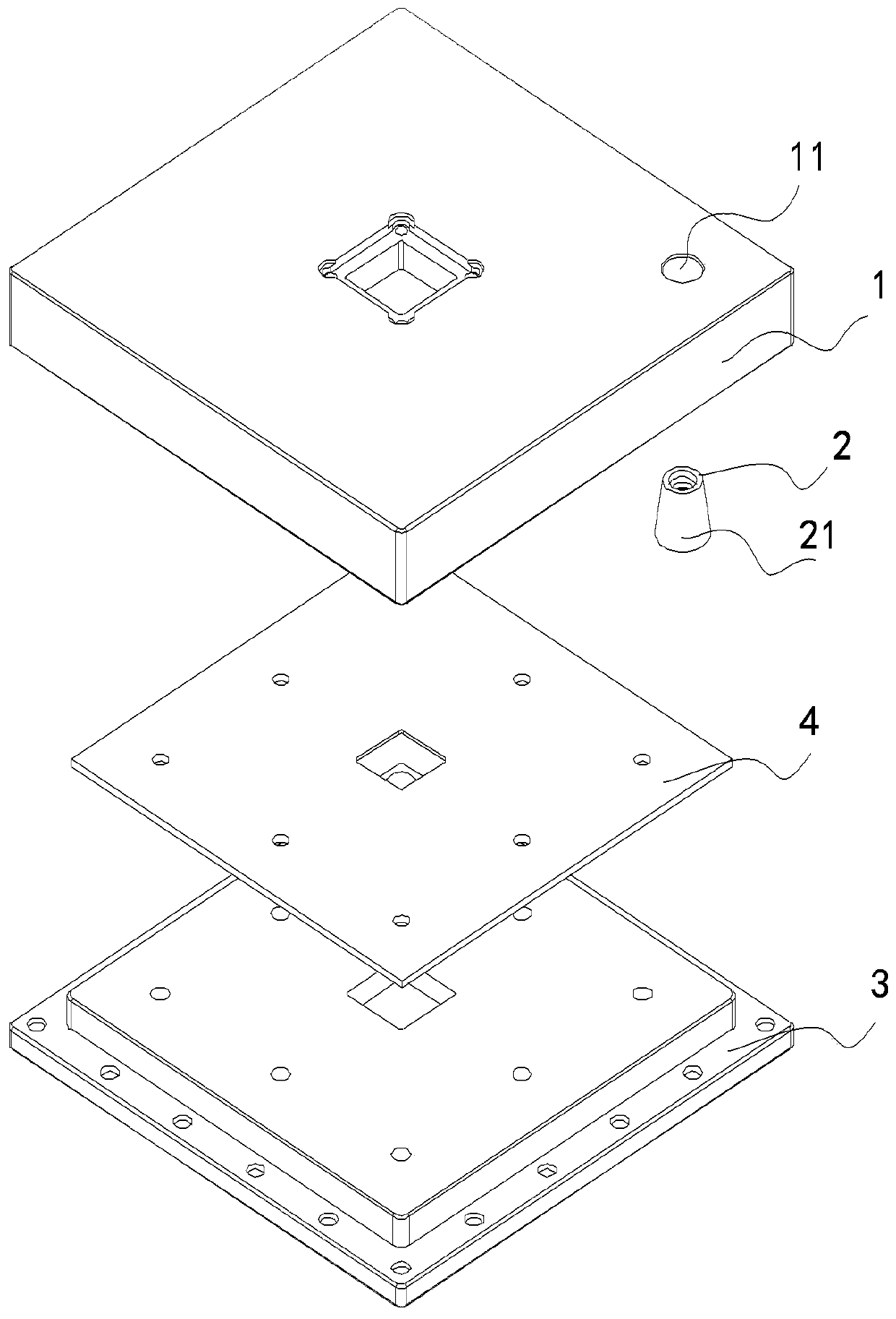
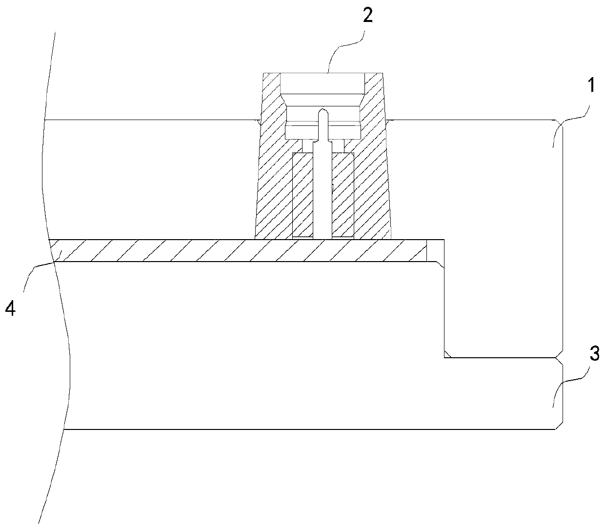
[0041] figure 1 It is an exploded structural schematic diagram of a signal connection structure based on shape protection as a component part of a packaging box according to an embodiment of the present disclosure. figure 2 As such figure 1 The signal connection structure shown is a partial cross-sectional structure diagram installed in the packaging box body.

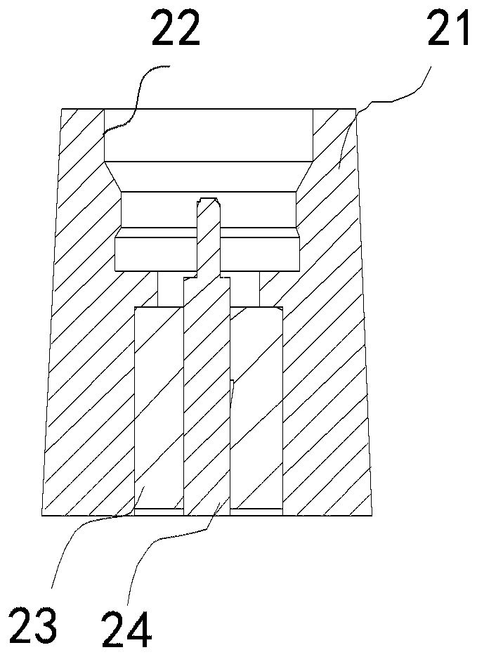
[0042] Reference figure 1 As shown, the signal connection structure based on shape protection of the present disclosure includes: a housing 1 on which a connector mounting hole 11 is provided; a signal connector 2 for mounting in the connector mounting hole 11, including The connector housing 21; wherein the connector housing 21 has a shape with a wide bottom and a narrow top, and the shape of the connector mounting hole 11 matches the shape of the connector housing 21.

[0043] The prese...

no. 2 example

[0057] In a second exemplary embodiment of the present disclosure, a signal connection structure based on shape protection is provided. In addition to the signal connection function, the signal connection structure also has the function of chip packaging.

[0058] In this embodiment, such as figure 2 As shown, the signal connection structure includes a first housing 1 as a package box for transmitting signals. A connector mounting hole 11 is provided on the first housing 1; a signal connector 2 is used for mounting on the The connector mounting hole 11 includes a connector housing 21; wherein the connector housing 21 has a shape with a wide bottom and a narrow top, and the shape of the connector mounting hole 11 matches the shape of the connector housing 21; The connection structure also includes: a second housing 3 arranged opposite to the first housing, the second housing 3 and the first housing 1 have complementary shapes to form a packaging box with an external seal and a sto...

no. 3 example

[0068] In the third exemplary embodiment of the present disclosure, a signal connection structure based on shape protection is provided. Compared with the structure of the second embodiment, the signal connection structure of this embodiment differs in that the two housings (the first housing and the second housing) of the signal connection structure of this embodiment are used for signal transmission. Expanded the signal output path. In this embodiment, the signal connection structure serves as both the top cover and the base of the packaging box body. The packaging box body includes a first shell and a second shell, and the opposite sides of the first shell and the second shell have complementary shapes. The second housing and the first housing form a packaging box with an external seal and an accommodating space inside. There are corresponding signal connectors on the first shell and the second shell, and both the first shell and the second shell are provided with connector...


PUM


Abstract

The invention discloses a signal connection structure based on shape protection, an assembling method thereof and a packaging box body, and the signal connection structure comprises a housing which isprovided with a connector installation hole; and signal connector which is used for being mounted in the connector installation hole and comprises a connector shell, wherein the connector shell is ina shape with a wide bottom and a narrow top, and the shape of the connector installation hole is matched with the shape of the connector shell. When the connector is subjected to external pulling force, most pulling force is borne due to the blocking of the shape of the shell, so that the pulling force borne by the welding position of the circuit board and the signal connector is reduced, the connection strength is improved, and the signal connector is protected; and in addition, due to the fact that the bottom of the connector shell is wide and the top of the connector shell is narrow, no linear gap exists between the signal connector and the shell, the possibility of light leakage is greatly reduced, photons cannot pass through smoothly, the shading effect is achieved, and therefore theeffects of avoiding light leakage and enhancing connection firmness are achieved at the same time.

Description

Technical field [0001] The present disclosure belongs to the technical field of integrated circuit packaging, and relates to a signal connection structure based on shape protection, an assembly method thereof, and a packaging box, in particular to a connection quantum chip with high reliability at extremely low temperatures (near absolute zero) A signal connection structure based on shape protection of an external signal connector and an assembly method thereof, and a quantum chip package box containing the signal connection structure. Background technique [0002] In the implementation of superconducting quantum computing, connecting the quantum processor with peripheral circuits is an indispensable step. The superconducting quantum processor package box is the first-level device connected with the quantum processor. How to connect and fan out the various performance pins of the superconducting quantum processor and ensure that the interference to the signal performance on the ...

Claims


Application Information

Patent Timeline
IPC IPC(8): H01R12/71H01R13/46H01R43/26H01L23/04H01L23/10H01L21/50
CPCH01R12/71H01R13/46H01R43/26H01L23/04H01L23/10H01L21/50
Inventor 梁福田沈慧妍邓辉龚明吴玉林彭承志朱晓波潘建伟
Owner UNIV OF SCI & TECH OF CHINA
Why Eureka
Try Eureka