Heat dissipation structure for display panel and preparation method and application of heat dissipation structure

A heat dissipation structure and display panel technology, which is applied in the construction of electrical equipment components, modification through conduction heat transfer, cooling/ventilation/heating transformation, etc., can solve the problems of thick panels and poor heat dissipation effects of display panels, and achieve improved Heat dissipation effect, thickness reduction, and overall thickness reduction effect

Inactive Publication Date: 2019-11-22
WUHAN CHINA STAR OPTOELECTRONICS SEMICON DISPLAY TECH CO LTD
View PDF5 Cites 3 Cited by
  • Summary
  • Abstract
  • Description
  • Claims
  • Application Information

AI Technical Summary

Problems solved by technology

[0006] An object of the present invention is to provide a heat dissipation structure for a display panel, which can solve the problems of poor heat dissipation and thicker panel thickness of the display panel in the prior art

Method used


Image

  • Heat dissipation structure for display panel and preparation method and application of heat dissipation structure
  • Heat dissipation structure for display panel and preparation method and application of heat dissipation structure
  • Heat dissipation structure for display panel and preparation method and application of heat dissipation structure

Examples


Embodiment 1

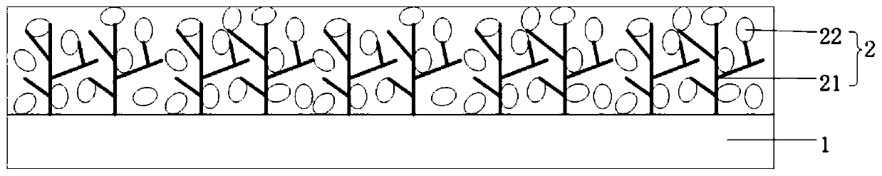
[0031] This embodiment provides a heat dissipation structure for a display panel, please refer to figure 2 , figure 2 Shown is a structural schematic diagram of the heat dissipation structure provided in this embodiment. The heat dissipation structure includes a copper foil layer 1 and a heat conduction layer 2 arranged on the copper foil layer 1, and the thickness of the heat conduction layer ranges from 50 μm to 150 μm.

[0032] The material used for the heat conduction layer 2 includes a heat conduction material 21 with a three-dimensional structure. In this embodiment, the three-dimensional structure of the heat conduction material 21 is a tree-like three-dimensional structure, and the material used is porous carbon. In other embodiments, the thermally conductive material 21 may also use carbon fiber network, which is not limited here.

[0033] The heat conduction material 21 with a tree-like three-dimensional structure establishes more heat diffusion channels, and the...

Embodiment 2

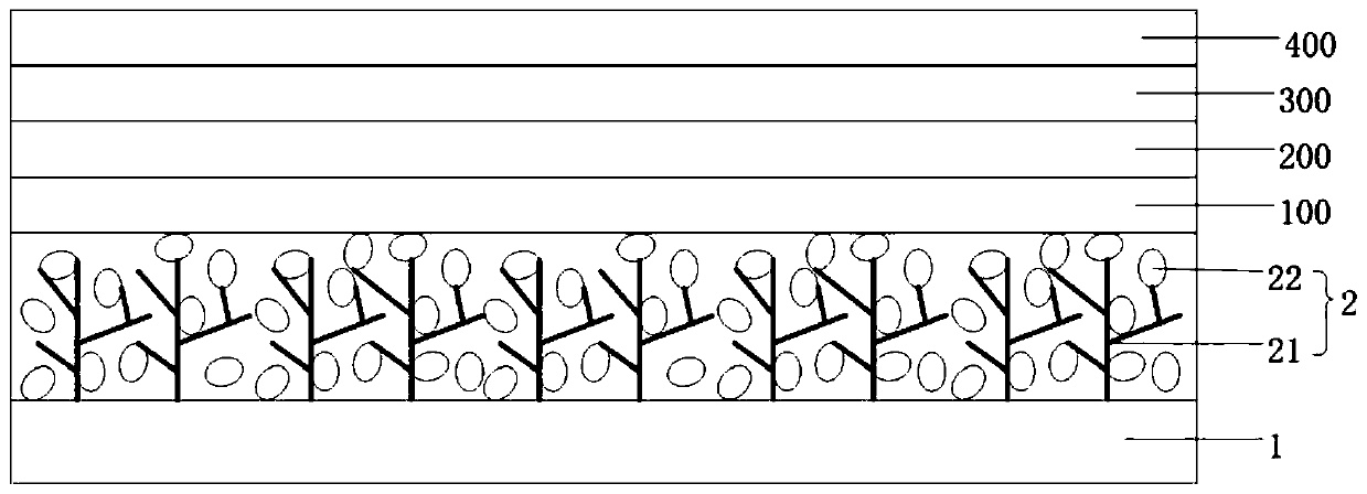
[0044] This embodiment provides a heat dissipation structure for a display panel, please refer to Figure 4 , Figure 4 Shown is a structural schematic diagram of the heat dissipation structure provided in this embodiment. The heat dissipation structure includes a copper foil layer 1 and a heat conduction layer 2 arranged on the copper foil layer 1, and the thickness of the heat conduction layer ranges from 50 μm to 150 μm.

[0045] The heat conduction layer 2 includes a one-dimensional heat conduction layer 21 and a two-dimensional heat conduction layer 22. The one-dimensional heat conduction layer 21 and the two-dimensional heat conduction layer 22 hybridize and grow to form a vertical three-dimensional structure. The heat conduction material used in the one-dimensional heat conduction layer 21 is a longitudinal nanotube. The heat conduction material used in the two-dimensional heat conduction layer 22 is a longitudinal nano-wall.

[0046] In other embodiments, the thermal...


PUM

PropertyMeasurementUnit
thicknessaaaaaaaaaa

Abstract

The invention provides a heat dissipation structure for a display panel and a preparation method and application of the heat dissipation structure. The heat dissipation structure comprises a copper foil layer and a heat conduction layer arranged on the copper foil layer, wherein the heat conduction layer is made of a heat conduction material with a three-dimensional structure, and gaps in the three-dimensional structure of the heat conduction material are filled with a buffering agent; a graphite layer with a lamellar structure and transverse heat conduction is replaced with the heat conduction layer with three-dimensional heat conduction; more thermal diffusion channels are established; the heat of the display panel can be quickly conducted along various paths and directly transmitted tothe copper foil layer, so that the heat conduction path is greatly shortened, and when part of longitudinal heat transfer channels are damaged, the heat can quickly find proper channels in the plane and then is longitudinally conducted; the heat conduction path is shortened, and the heat dissipation effect is improved.

Description

technical field [0001] The invention relates to the technical field of display panels, in particular to a heat dissipation structure for a display panel, a preparation method and application thereof. Background technique [0002] Due to its low power consumption, high resolution, fast response, and bendability, flexible OLED displays are a popular development direction in the display industry. The thinner the OLED display, the greater its market competitiveness. At present, flexible materials such as polyimide film (PolyimideFilm, PI) or polyethylene terephthalate (PET) are often used as substrates, on which thin film crystal diodes (Thin film transistor, TFT), OLED , Thin film encapsulation (TFE), and then continue bongding polarizer and glass cover on top. In order to drive the TFT, it is necessary to bongding the chip circuit at the bottom of the flexible substrate to form a display panel. [0003] When the display is working, the current passing through the TFT circuit...

Claims


Application Information

Patent Timeline
Patent Type & Authority Applications(China)
IPC IPC(8): H05K7/20
CPCH05K7/20954H05K7/2039H05K7/20963H05K7/20481
Inventor 王一佳
Owner WUHAN CHINA STAR OPTOELECTRONICS SEMICON DISPLAY TECH CO LTD
Why Eureka
Try Eureka