
Medical wastewater treatment method

A wastewater treatment and plasma technology, applied in the field of medical wastewater treatment, can solve the problems of slow non-equilibrium plasma purification rate, failed electrodes, corrosion, etc., and achieve the effects of low pathogen regeneration rate, low use cost, and improved purification flow

Active Publication Date: 2019-11-29
DALIAN NATIONALITIES UNIVERSITY
View PDF6 Cites 1 Cited by
  • Summary
  • Abstract
  • Description
  • Claims
  • Application Information

AI Technical Summary

Problems solved by technology

[0003] Aiming at the problems in the prior art that the non-equilibrium plasma purification rate is too slow, or even fails, as well as electrode corrosion and failure, this application proposes a medical wastewater treatment method

Method used


Image

  • Medical wastewater treatment method
  • Medical wastewater treatment method
  • Medical wastewater treatment method

Examples


Embodiment 1

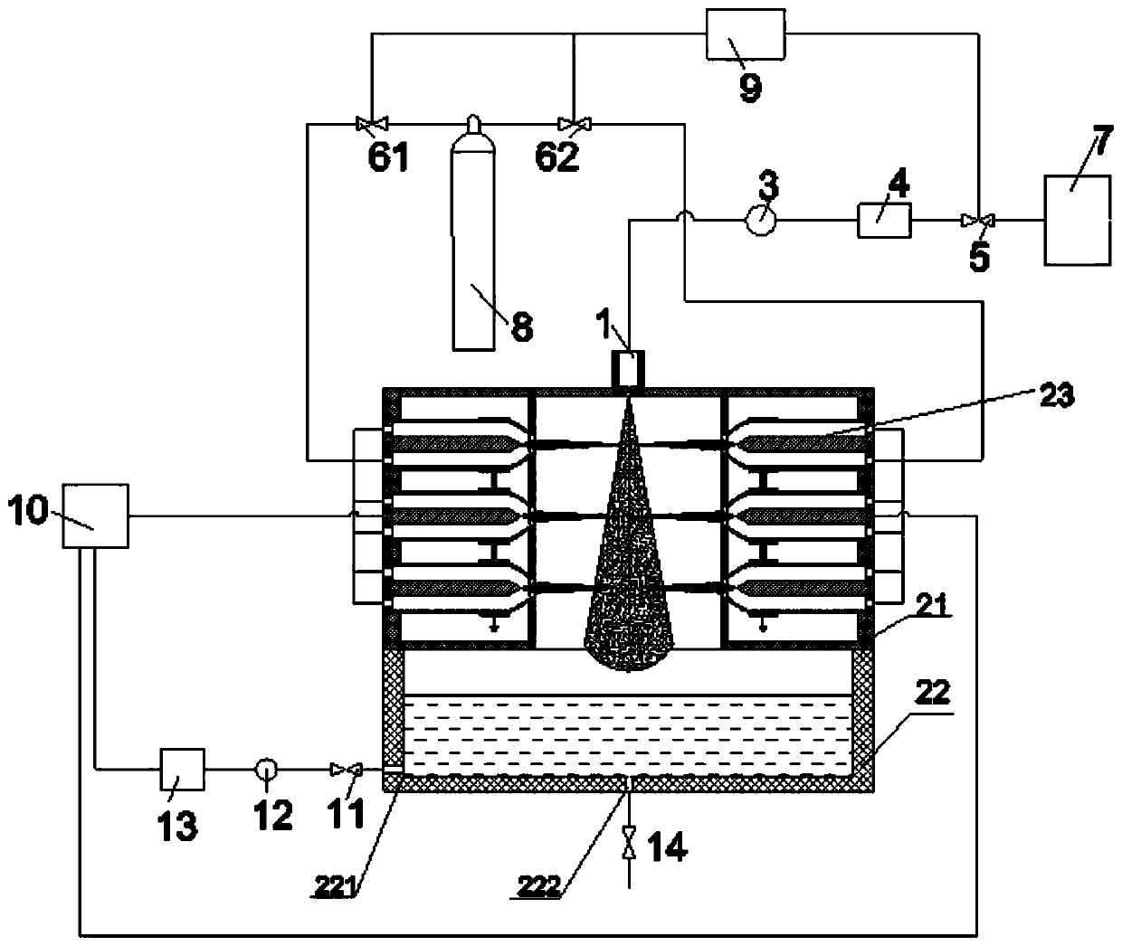
[0032] This embodiment provides a medical wastewater treatment method, which specifically includes the following steps:

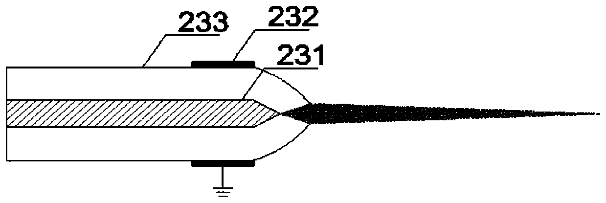
[0033] S1. A multi-layer unbalanced plasma jet exciter is arranged on the body of the jet purifier, and a plurality of unbalanced plasma jet exciters placed on each layer are distributed in a circle; the unbalanced plasma jet exciter includes a high-voltage electrode, grounding An electrode and an exciter body, the high-voltage electrode is located in the exciter body, and a ground electrode is connected to the outer wall of the exciter body;

[0034] S2. The plasma power supply supplies power to each high-voltage electrode, and forms an electric field in the space between the corresponding high-voltage electrode and the ground electrode to discharge;

[0035] S3. The valve opening electronic controller controls the gas flow control valve a and the gas flow control valve b to open, and the high-pressure gas in the high-pressure gas cylinder enters the corre...

Embodiment 2

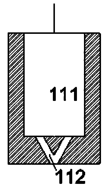
[0044] This embodiment provides a medical wastewater treatment device, including: a liquid processor, an array type unbalanced plasma jet purifier, a liquid flow meter to be purified, a filter, a liquid flow control valve, a gas flow control valve a, a gas flow control Valve b, liquid storage tank, high-pressure gas cylinder, valve opening electronic controller, plasma power supply, detection port control valve, detection port return pump, detection unit and water treatment box; the array type unbalanced plasma jet purifier It includes a jet purifier body, on which a multi-layer unbalanced plasma jet actuator is arranged, and a plurality of unbalanced plasma jet exciters arranged on each layer are distributed in a circle; the liquid processor passes through the to-be-purified The liquid flow meter, filter, and liquid flow control valve are connected to the liquid storage tank, and the liquid flow control valve is also connected to one end of the valve opening electronic control...


PUM


Abstract

The invention discloses a medical wastewater treatment method which comprises the following steps: S1, arranging multiple layers of non-balance plasma jet flow stimulator on a jet flow purifier; S2, supplying power to each high-voltage electrode through a plasma power supply; S3, controlling a gas flow control valve a and a gas flow control valve b to be opened by a valve opening degree electroniccontroller; S4, controlling a liquid flow control valve to be opened by a valve opening degree electronic controller, and feeding a liquid to be treated in a liquid storage tank into an action spaceof array non-balance plasma jet flows; S5, under the action of the non-balance plasma jet flow, killing a target purification substance in liquid droplet granules in an atomization field; S6, collecting liquid spray purified by the array non-balance plasma jet flows in a water treatment tank; and S7, opening a detection hole control valve, pumping out a liquid after purification by using a detection hole refluxing pump, and feeding the liquid into a detection unit. The non-balance plasma technique has the characteristics of being high in killing efficiency, low in pathogene regeneration rate,low in use cost, and the like, and is a completely new efficient and clean water purification technique.

Description

technical field [0001] The invention relates to a method for treating medical wastewater. Background technique [0002] At present, the source and composition of hospital sewage are complex and harmful. The main source is the sewage discharged from the hospital's diagnosis and treatment rooms, laboratories, wards, laundry rooms, X-ray photography rooms and operating rooms. Sewage contains a large number of pathogenic bacteria, viruses and agents, and has the characteristics of space pollution, acute infection and latent infection. If hospital sewage containing pathogenic microorganisms is discharged into urban sewers or environmental water bodies without disinfection treatment, it will often cause water pollution, cause various diseases and infectious diseases, and seriously endanger people's health. When non-equilibrium plasma technology is used to treat medical wastewater, the liquid flow rate is too small due to the small size of the ionization space (that is, the apertu...

Claims


Application Information

Patent Timeline
Patent Type & Authority Applications(China)
IPC IPC(8): C02F1/46C02F101/30
CPCC02F1/4608C02F2103/003C02F2101/30C02F2201/46C02F2209/38C02F2209/40C02F2303/04C02F2303/14
Inventor 宋鹏
Owner DALIAN NATIONALITIES UNIVERSITY
Learn More