
Numerical control rotary table geometric error measurement method based on four-base-station laser tracking system

A technology of geometric error and numerical control turntable, which is applied in the direction of measuring device, mechanical measuring device, measuring/indicating equipment, etc., can solve the problems of difficult adjustment of optical path, low measurement accuracy, and dependence on operators, etc., and achieves wide application range and high detection accuracy , the effect of high measurement accuracy

Active Publication Date: 2019-12-03
XI AN JIAOTONG UNIV
View PDF8 Cites 16 Cited by
  • Summary
  • Abstract
  • Description
  • Claims
  • Application Information

AI Technical Summary

Problems solved by technology

Laser interferometers are mostly used to measure the positioning error of the turntable, and it is difficult to adjust the optical path during the measurement process. The process needs to adjust the eccentricity, the adjustment is time-consuming and the test range is small, and the measurement accuracy is low

Method used


Image

  • Numerical control rotary table geometric error measurement method based on four-base-station laser tracking system
  • Numerical control rotary table geometric error measurement method based on four-base-station laser tracking system
  • Numerical control rotary table geometric error measurement method based on four-base-station laser tracking system

Examples


Embodiment Construction

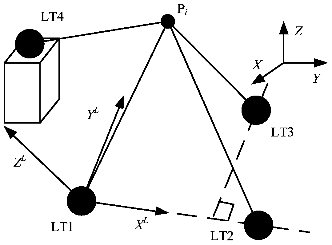
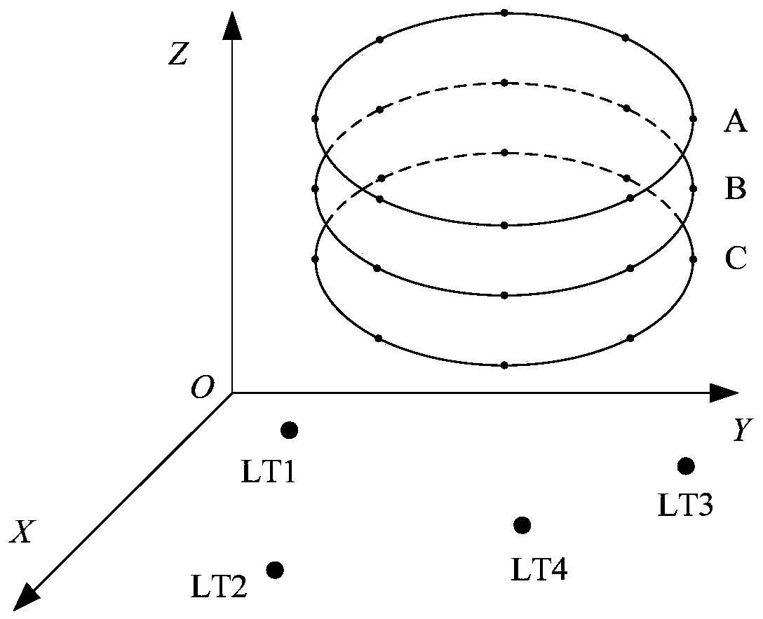
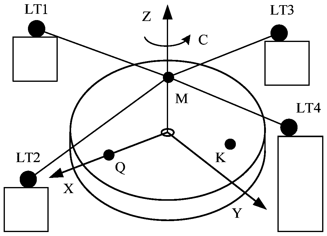
[0044]The invention provides a numerical control turntable geometric error measurement method based on a four-base laser tracking system. The four-base laser tracking interferometer is used to establish a laser tracking interferometer self-calibration coordinate system, and the cylindrical surface composed of three points at different heights is used to complete the measurement. Calibrate the position parameters of the laser tracking interferometer, and complete the measurement of the target point. The turntable is measured by rotating the turntable at a certain angle interval for three points that are not coplanar. The coordinate system of the turntable is established by using the coordinates of the measured points, and according to the translation The coordinates of the measuring points in the turntable coordinate system are obtained by the change of the rotation matrix, the theoretical point coordinates are calculated by using the fitted radius of the turntable, and the spati...


PUM


Abstract

The invention discloses a numerical control rotary table geometric error measurement method based on a four-base-station laser tracking system, and the method comprises the steps: building a self-calibration coordinate system, and calibrating the position of a tracking interferometer; respectively placing the target mirrors at three non-coplanar points on a rotary table, keeping a certain distancefrom the rotary table, controlling the rotary table to rotate according to a certain angle interval, and solving by using a nonlinear least square method to obtain coordinates of a measurement pointunder the self-calibration coordinate system; after the measurement is finished, fitting to obtain a circle center of a space circle formed by the three points and a radius fitting function; establishing a coordinate system of the rotary table; subtracting the coordinates of the theoretical point from the coordinates of the actual measurement point under the coordinate system of the rotary table to obtain the spatial position errors of the measurement point, and obtaining the six geometric errors of the rotary table by utilizing the spatial position errors of the three points at the same position through establishing a six-position-related geometric error model of the rotary table. The method has the advantages of short detection time, high detection precision and low detection uncertainty, and can be used for rotary table error detection of a precision numerical control machine tool.

Description

technical field [0001] The invention belongs to the technical field of geometric error measurement of a numerical control turntable, and in particular relates to a method for measuring the geometric error of a numerical control turntable based on a laser tracking system of four base stations. Background technique [0002] With the continuous development of modern manufacturing industry and national defense industry, precision and ultra-precision machining and manufacturing technology demand more and more high-end multi-axis CNC machine tools with ultra-high-precision rotating shafts, especially in inertial confinement nuclear fusion, earth observation, Manufacturing of large-aperture optical free-form surface components required for national defense such as lidar and EUV lithography. The geometric accuracy of the rotation axis directly affects the key optical performance indicators such as the axis position, surface shape accuracy, and surface roughness of the large optical ...

Claims


Application Information

Patent Timeline
IPC IPC(8): B23Q17/24G01B11/00
CPCB23Q17/24G01B11/00G01B11/002G01B21/042G01B5/0004B23Q17/2495B23Q2220/004G01B9/02083G01B11/005
Inventor 查俊陈耀龙韩林
Owner XI AN JIAOTONG UNIV
Learn More