Laser cladding method for processing debris

A laser cladding and chipping technology, applied in the field of surface engineering, can solve the problems of high manufacturing cost and high manufacturing cost, and achieve the effect of saving manufacturing cost, reducing remelting, and having significant economic effect.

Pending Publication Date: 2019-12-06
TIANJIN UNIV OF TECH & EDUCATION TEACHER DEV CENT OF CHINA VOCATIONAL TRAINING & GUIDANCE
View PDF1 Cites 1 Cited by
  • Summary
  • Abstract
  • Description
  • Claims
  • Application Information

AI Technical Summary

Problems solved by technology

However, the high cost of manufacturing due to the high cost of laser cladding materials is one of the main reasons that limit its wide application. Reducing the cost of cladding is a major problem to be solved in the field of manufacturing

Method used


Image

  • Laser cladding method for processing debris
  • Laser cladding method for processing debris
  • Laser cladding method for processing debris

Examples


example 1

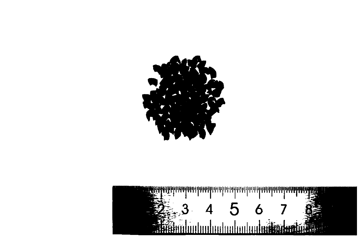
[0024] (1) Recover the debris generated by the turning process of 30CrMnSi, and use alcohol cleaning to remove the oil and impurities on the surface of the debris. Processing debris such as figure 1 shown

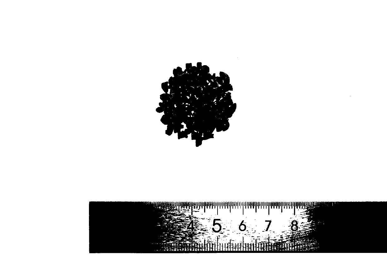
[0025] (2) After the debris is dried, use a high-energy ball mill for mechanical treatment. The mass ratio of the ball to material is 10:1, and the treatment time is 8 hours. The oxide layer on the surface of the debris is removed, and then the surface attachment is removed by alcohol cleaning. Remove scale debris such as figure 2 as shown, Figure 4 It is the SEM morphology after descaling.

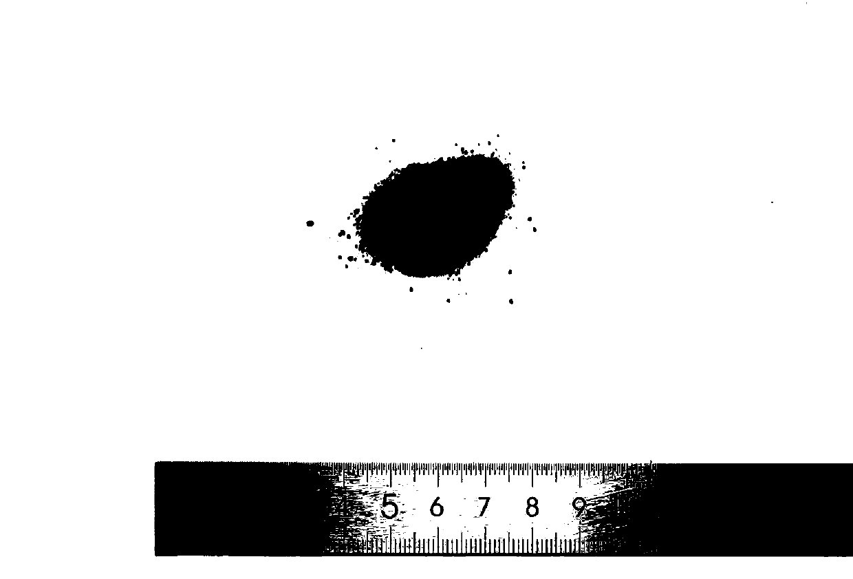
[0026] (3) Remove scale debris and dry, then use ball mill for mechanical treatment again, the ratio of ball to material is 10:1, and the ball milling time is 35h, until the debris is mechanically stirred into powder. crushed powder such as image 3 shown.

[0027] (4) Dry the powder formed after crushing the debris. The treatment temperature is 200°C and the time is 2h. Use a ...

example 2

[0030] (1) Recover the debris produced by the turning process of 30CrMnSi, and carry out pretreatment according to the method of Example 1. Processing debris such as figure 1 shown

[0031] (2) After the debris is dried, use a high-energy ball mill for mechanical treatment. The mass ratio of the ball to material is 14:1, and the treatment time is 10 hours. The oxide layer on the surface of the debris is removed, and then the surface attachment is removed by alcohol cleaning.

[0032] (3) Remove scale debris and dry, then use ball mill for mechanical treatment again, the ratio of ball to material is 14:1, and the ball milling time is 40h, until the debris is mechanically stirred into powder.

[0033] (4) Treat with the method of Example 1, dry the powder formed after crushing the debris, the treatment temperature is 200°C, and the time is 2h. Use a sieve to distinguish two types of powders, and the size of the first type is in the range of 100-300 mesh ( 48-150μm) within the ...

example 3

[0036] (1) Recover the debris produced by the turning process of 30CrMnSi, and carry out pretreatment according to the method of Example 1. Processing debris such as figure 1 shown

[0037] (2) After the debris is dried, use a high-energy ball mill for mechanical treatment. The mass ratio of the ball to material is 14:1, and the treatment time is 10 hours. The oxide layer on the surface of the debris is removed, and then the surface attachment is removed by alcohol cleaning.

[0038] (3) Remove scale debris and dry, then use ball mill for mechanical treatment again, the ratio of ball to material is 14:1, and the ball milling time is 40h, until the debris is mechanically stirred into powder.

[0039] (4) Treat with the method of Example 1, dry the powder formed after crushing the debris, the treatment temperature is 200°C, and the time is 2h. Use a sieve to distinguish two types of powders, and the size of the first type is in the range of 100-300 mesh ( 48-150μm) within the ...


PUM


Abstract

The invention provides a laser cladding method for recovering and reusing processing debris. In order to overcome the problem of high price of laser cladding powder. The laser cladding method selectsto recover a turning processing debris, uses high-energy ball milling mechanical agitation to remove an oxide film on the surface of a powder material, continues high-energy ball milling and agitationafter cleaning, until the debris is crushed into powder, so as to replace the laser cladding material to realize the secondary reuse of waste material. Finally, the powder is preset with the surfaceof the base material, and the coating is prepared by the laser cladding equipment. The laser cladding method adapts the method of reusing the turning processing debris, so that the manufacturing costof laser cladding powder is saved and the utilization rate of resources is improved; and is a green manufacturing mode with significant benefits.

Description

technical field [0001] The invention belongs to the field of surface engineering, and relates to a laser cladding method for recycled processing debris. Background technique [0002] Laser cladding technology is an emerging surface modification and processing technology. It uses laser beams as heat sources to melt alloy powders and forms a metallurgical bonded surface coating on the surface of the base alloy. Its research history originated in the 1970s. In the 1980s, laser cladding technology has developed into a frontier topic in the fields of surface engineering, tribology, and applied lasers. After the 1990s, related scientific research and application development have been rapidly developed. develop. As an effective means of material surface modification technology, laser cladding technology can significantly improve the strength, hardness, wear resistance, high temperature oxidation resistance, corrosion resistance and other properties of the surface of metal material...

Claims


Application Information

Patent Timeline
Patent Type & Authority Applications(China)
IPC IPC(8): C23C24/10B09B3/00
CPCC23C24/106B09B3/00
Inventor 李洋谭娜蔡玉俊王浩王琳宁
Owner TIANJIN UNIV OF TECH & EDUCATION TEACHER DEV CENT OF CHINA VOCATIONAL TRAINING & GUIDANCE
Why Eureka
Try Eureka