
Superheat water vapor in-situ pyrolysis oil-rich coal efficient oil extraction method

A technology of superheated steam and in-situ pyrolysis, which is applied in earth-moving drilling, fluid production, wellbore/well components, etc. effect of time, diffusion reduction, and pyrolysis temperature increase

Inactive Publication Date: 2019-12-06
XIAN UNIV OF SCI & TECH
View PDF9 Cites 19 Cited by
  • Summary
  • Abstract
  • Description
  • Claims
  • Application Information

AI Technical Summary

Problems solved by technology

Because the crushing technology of this process is limited to local oil shale reservoir transformation, the heat carried by the fluid is not fully utilized, resulting in a lower heating efficiency

Method used


Image

  • Superheat water vapor in-situ pyrolysis oil-rich coal efficient oil extraction method
  • Superheat water vapor in-situ pyrolysis oil-rich coal efficient oil extraction method
  • Superheat water vapor in-situ pyrolysis oil-rich coal efficient oil extraction method

Examples


Embodiment 1

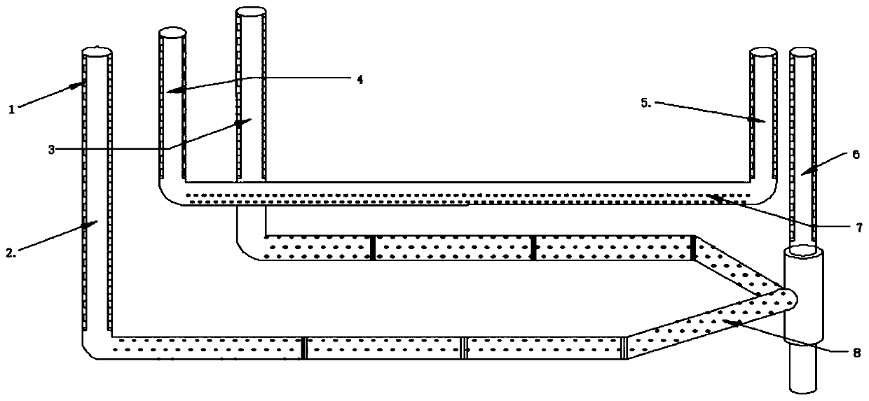
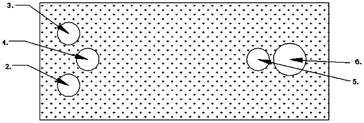
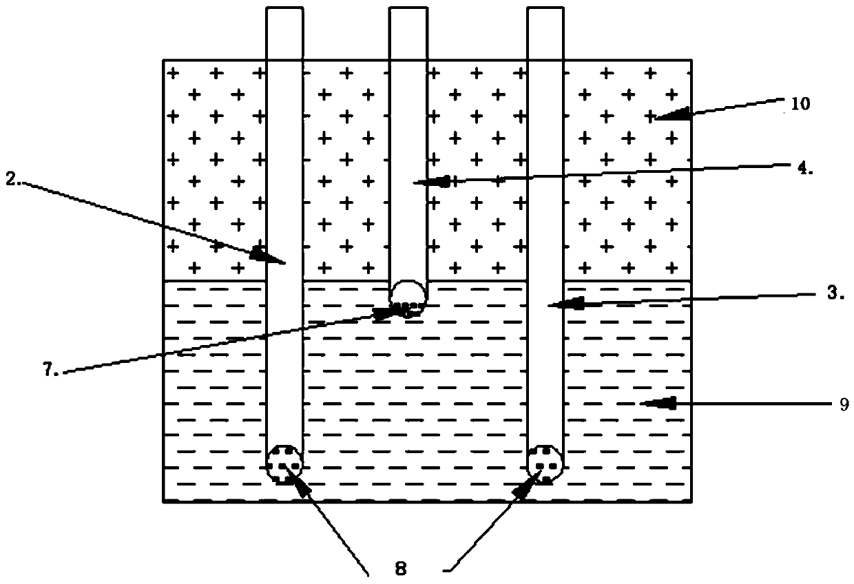
[0033] like Figure 1-4 As shown, in the method of this embodiment, the vertical well 6 is first drilled, and two horizontal wells are drilled as heat injection wells A and B again. , B is connected with vertical shaft 6, the elevation of the coal-seeing section of the heat injection horizontal well is greater than that of the vertical well. Channel, production well A is drilled above heat injection wells A and B, and the horizontal well distance of production well A is greater than 500m, of which 500m refers to the horizontal distance of the production well in the coal seam, production well A and production well B are connected, and the production well A uses a screen tube, and water or supercritical carbon dioxide is introduced through the heat injection wells A and B, and the coal seam is fractured by the process of staged perforation and staged fracturing respectively, and the mixed slurry of iron ore and lime is injected in stages. After the completion of the perforation...

Embodiment 2

[0035] Compared with Embodiment 1, the fracturing method of this embodiment is different from that of Embodiment 1. Embodiment 1 adopts hydraulic fracturing, while this embodiment adopts controllable shock wave fracturing. Different, it will affect the subsequent injection of steam and limestone slurry, which will affect the pyrolysis efficiency and oil production rate of oil-rich coal. Embodiment 2 will be specifically described below.

[0036] like Figure 1-4As shown in the figure, the vertical well 6 is drilled, and two horizontal wells are drilled as heat injection wells A and B again. The heat injection wells are run with casing. The distance between the horizontal wells of the heat injection wells A and B is greater than 500m, and the heat injection wells A and B are communicated with the vertical well 6. , the elevation of the coal-seeing section of the heat-injection horizontal well is greater than that of the vertical shaft. The vertical well can effectively dischar...


PUM


Abstract

The invention relates to a superheat water vapor in-situ pyrolysis oil-rich coal efficient oil extraction method. In the method, the well spacing manner of two horizontal heat injection wells and onehorizontal production well is adopted, and hydrofracture / supercritical carbon dioxide fracture / controllable shock wave fracture technology is adopted, a large-scale grid fractures is formed inside thecoal layer, and blended grout of iron ore and lime is injected in the fractures to improve the thermal conductivity of oil-rich coal and heat uniformity of the oil-rich coal; and low-temperature plasma electrodes are planted in the horizontal sections of the two heat injection wells, and auxiliary pyrolysis to oil-rich coal is carried out through adopting the low-temperature plasma technology. According to the invention, a reliable heat source is provided, the heat conduction efficiency is improved, underground pyrolysis temperature is maintained while increasing the capability of gas bearingand oil gas bearing, and the pyrolysis oil preparation efficiency and light oil proportion of the oil-rich coal are improved.

Description

technical field [0001] The invention relates to a high-efficiency oil-lifting method for oil-rich coal, belonging to the technical field of energy application, in particular to a high-efficiency oil-lifting method for in-situ pyrolysis of oil-rich coal with superheated water steam. Background technique [0002] Coal (air drying base) can be divided into three grades according to the low temperature tar yield grade of coal. Coal with low temperature tar yield ≤7% is called oily coal, and coal with low temperature tar yield greater than 7% and less than or equal to 12% is called oily coal. Oil-rich coal, coal with low temperature tar yield > 12% is high oil coal. Through low temperature dry distillation technology, oil and gas in oil-rich coal can be separated and extracted, which can be used to make up for practical problems such as lack of oil, lack of gas and scarcity of coking coal. [0003] At present, the technology used for coal dry distillation is ground dry distil...

Claims


Application Information

Patent Timeline
Patent Type & Authority Applications(China)
IPC IPC(8): E21B43/241E21B43/26E21B43/34
CPCE21B43/241E21B43/26E21B43/34
Inventor 王双明石智军王生全张蕾
Owner XIAN UNIV OF SCI & TECH
Learn More