Medium and deep layer geothermal energy collection same well withdrawing system

A deep ground and thermal energy technology, applied in geothermal energy, heating system, geothermal energy power generation, etc., can solve the problems of large site occupation, sand removal, geological subsidence, etc., to achieve easy on-site installation, safe and reliable operation, and less land occupation Effect

Pending Publication Date: 2019-12-06
河南省宇基环保科技有限公司
View PDF0 Cites 2 Cited by
  • Summary
  • Abstract
  • Description
  • Claims
  • Application Information

AI Technical Summary

Problems solved by technology

[0003] It is a clean energy heating method to use the heat energy of underground water sources to heat the living room or commercial places. It has been widely used in recent years. There are some problems in the existing energy collection system of water source heat pump central air conditioners: 1. Generally, the mode of one pumping and multiple cycles is adopted. The drawback is that the long-term use of the well can not be fully recharged, which will cause the groundwater level to drop, and sand will be displaced during use, and long-term use will easily cause geological subsidence and other adverse effects; It occupies a large space and costs high; 3. Generally, shallow geothermal energy is used as a heat source, and the extracted heat is 15-18°C. The heat source conversion rate is not high, and the heating effect is not ideal

Method used


Image

  • Medium and deep layer geothermal energy collection same well withdrawing system
  • Medium and deep layer geothermal energy collection same well withdrawing system
  • Medium and deep layer geothermal energy collection same well withdrawing system

Examples


Embodiment 1

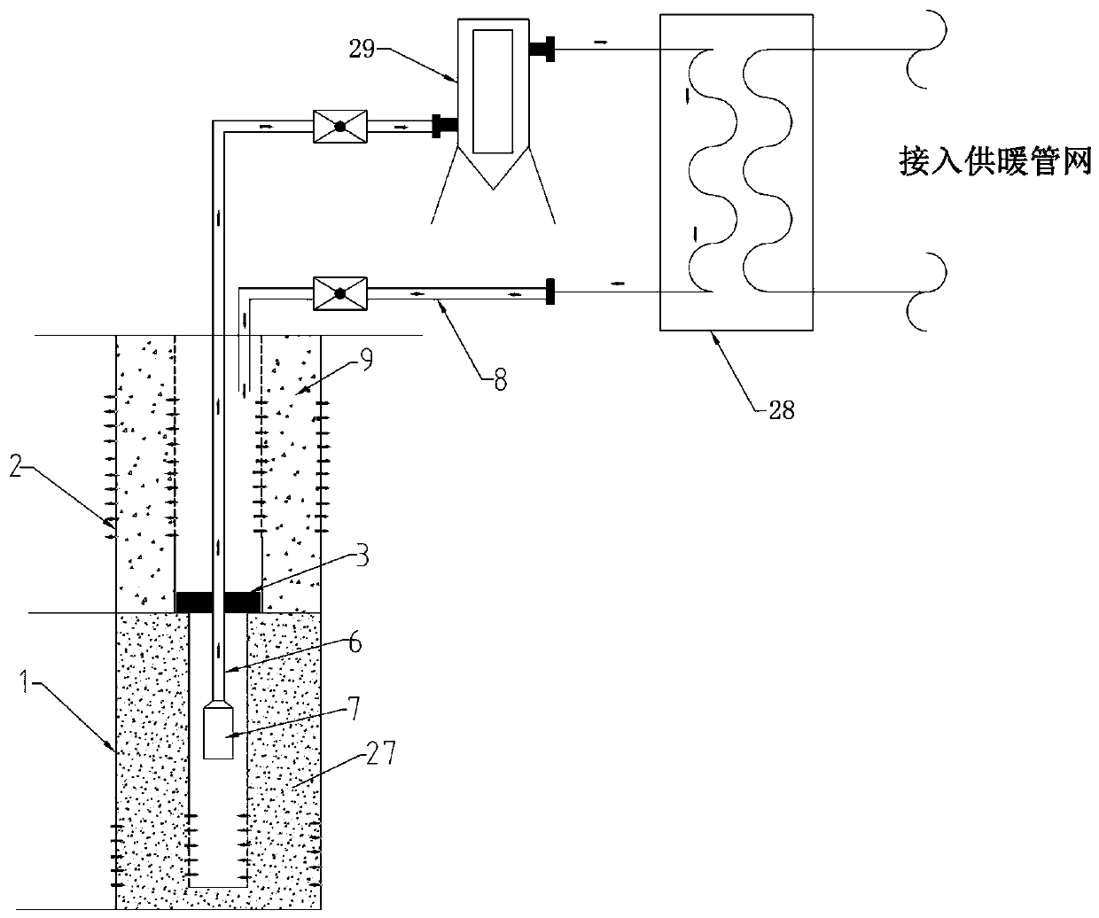
[0040] Example 1: A medium-deep geothermal energy collection and extraction system in the same well, see figure 1 , figure 2 , including collection wells and heat exchange components.

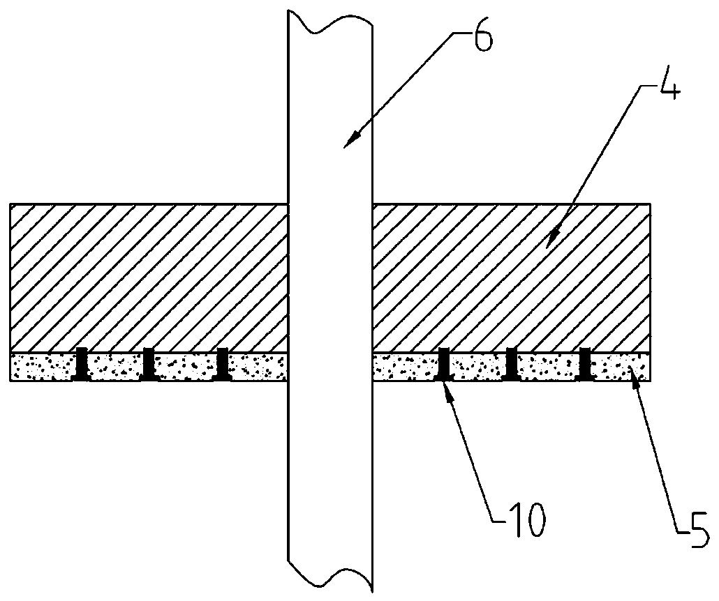
[0041] The collection well includes a well body, and the well body includes a lower thermal energy extraction zone 1 and an upper recharge zone 2. The diameter of the wellbore in the thermal energy extraction zone 1 is smaller than that in the recharge zone 2. Between the thermal energy extraction zone 1 and the recharge zone 2 A closing device 3 is provided adjacent to the , and the closing device 3 includes a load-bearing steel plate 4 and a sealing rubber plate 5 fixedly arranged on the lower surface of the load-bearing steel plate 4. The sealing rubber plate 5 is fastened together with the load-bearing steel plate 4 through fixing bolts 10, and the closed The device 3 is arranged on the top of the well hole in the heat extraction area 1; in the center of the load-bearing steel plate 4, th...


PUM

PropertyMeasurementUnit
diameteraaaaaaaaaa
diameteraaaaaaaaaa
depthaaaaaaaaaa

Abstract

The invention discloses a medium and deep layer geothermal energy collection same well withdrawing system. A collection well and a heat exchanging assembly are included; the collection well comprisesa well body which comprises a lower heat energy extraction area and an upper recharging area; the adjacent position between the heat energy extraction area and the recharging area is provided with a closing device; the center of the closing device is provided with a through hole used for a water pumping pipe to pass through; the lower end of the water pumping pipe extends into the heat energy extraction area; the lower end of the water pumping pipe is connected with a submersible pump used for pumping geothermal water; the position between the outer side of a well pipe of the recharging area and the inner wall of a well hole is filled with a quartz sand filtering material layer; and the heat exchanging assembly comprises a filtering purification device and a heat exchanger. The collectionwell with the water pumping and water returning functions is adopted, the heat in the medium and deep layer geothermal water is collected and utilized, but the geothermal water is not consumed, the geothermal water is high in recharging rate after heat exchanging, lowering of an underground water level cannot be caused, and changing and damage of a geologic structure cannot be caused. The medium and deep layer geothermal energy collection same well withdrawing system is small in occupied area, convenient to construct and maintain, lower in cost and higher in resource utilizing rate.

Description

technical field [0001] The invention relates to the technical field of geothermal energy collection, in particular to a mid-deep geothermal energy collection and extraction system in the same well. Background technique [0002] In recent years, the problem of air pollution in my country has become increasingly serious, and the regional atmospheric environment problems characterized by inhalable particulate matter (PM10) and fine particulate matter (PM2.5) are particularly prominent. , the consumption of energy resources continues to increase, and the pressure on air pollution prevention and control continues to increase. [0003] It is a clean energy heating method to use the heat energy of underground water sources to heat the living room or commercial places. It has been widely used in recent years. There are some problems in the existing energy collection system of water source heat pump central air conditioners: 1. Generally, the mode of one pumping and multiple cycles is...

Claims


Application Information

Patent Timeline
Patent Type & Authority Applications(China)
IPC IPC(8): F24D3/10F24T10/10B01D24/12B01D24/46
CPCB01D24/12B01D24/46F24D3/10F24T10/10Y02E10/10
Inventor 冯卫红
Owner 河南省宇基环保科技有限公司
Why Eureka
Try Eureka