
Natural gas autothermal reforming proton exchange membrane fuel cell distributed cogeneration system and method

A proton exchange membrane and fuel cell technology, applied in fuel cell heat exchange, fuel cells, fuel cell additives, etc., can solve the problems of limiting the large-scale application of fuel cells, difficult utilization, and large energy

Pending Publication Date: 2019-12-06
HUADIAN ELECTRIC POWER SCI INST CO LTD
View PDF1 Cites 7 Cited by
  • Summary
  • Abstract
  • Description
  • Claims
  • Application Information

AI Technical Summary

Problems solved by technology

However, the large-scale application of fuel cells is limited to a certain extent due to the limitations of pure hydrogen in terms of price, safety, storage, and transportation; A new way to promote the application of fuel cells at this stage
There are many technical routes for hydrogen production from natural gas reforming, including steam reforming, autothermal oxidation reforming, partial oxidation, and natural gas direct cracking. Autothermal reforming combines the endothermic reaction of steam reforming with the exothermic reaction of partial oxidation. It can minimize fuel consumption and has good dynamic characteristics; in addition, in practical applications, the comprehensive fuel utilization rate of PEMFC power generation system is not high, mainly because the power generation efficiency of proton exchange membrane fuel cells is affected by various operations. Influenced by parameters, at the same time, a large amount of heat is generated in the process of power generation. This part of waste heat is of low grade and difficult to use, but the energy is large, accounting for about 40% to 60% of the total energy.

Method used


Image

  • Natural gas autothermal reforming proton exchange membrane fuel cell distributed cogeneration system and method
  • Natural gas autothermal reforming proton exchange membrane fuel cell distributed cogeneration system and method
  • Natural gas autothermal reforming proton exchange membrane fuel cell distributed cogeneration system and method

Examples


Embodiment Construction

[0047] The present invention will be further described in detail below in conjunction with the accompanying drawings and examples. The following examples are explanations of the present invention and the present invention is not limited to the following examples.

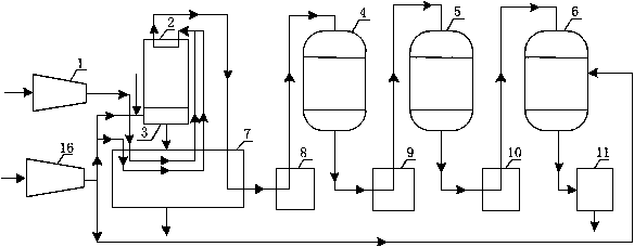
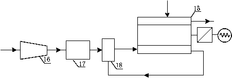
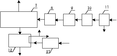
[0048] Such as Figure 5 As shown, the natural gas autothermal reforming proton exchange membrane fuel cell distributed heat and power cogeneration system provided in this embodiment includes a supercharger 1, an autothermal reformer 2, a burner 3, a high-temperature shift reactor 4, and a low-temperature Shift reactor 5, CO oxidation reactor 6, #5 integrated heat exchanger 7, #4 heat exchanger 8, #3 heat exchanger 9, #2 heat exchanger 10, #1 heat exchanger 11, #6 heat exchanger Water heat exchanger 12, temperature rise type heat pump unit 13, circulating water pump 14, proton exchange membrane fuel cell body 15, air compressor 16, air cooler 17, humidifier 18, inverter 19.

[0049] The natural gas outlet of the na...


PUM


Abstract

The invention relates to a natural gas autothermal reforming proton exchange membrane fuel cell distributed cogeneration system and method. The system includes a natural gas autothermal reforming module, a proton exchange membrane fuel cell module, an autothermal reforming exhaust gas heat utilization module, a fuel cell waste heat utilization module, and a connection pipeline. The system inputs anatural gas, air, and working water, and outputs power and multistage heat to achieve high-efficiency cogeneration. The natural gas comes directly from an existing urban pipe network. By autothermalsteam reforming, a coupled endothermic steam reforming reaction and an exothermic partial oxidation reaction, self heat supply is achieved in the system. High and low temperature steam conversion andpreferential oxidation technology is used to product a hydrogen-rich gas for fuel cells, which electrochemical reacts with a pressurized self-humidified air entering a fuel cell stack system to outputelectricity. In addition, the waste heat of the system is used in multiple stages to form a clean and efficient natural gas autothermal reforming proton exchange membrane fuel cell distributed cogeneration system.

Description

technical field [0001] The invention relates to a distributed heat and power cogeneration system of natural gas autothermal reforming proton exchange membrane fuel cell. Thermal partial oxidation reaction to realize self-heating of the system, high-low temperature steam shift and preferential oxidation technology to produce hydrogen-rich gas for fuel cells, and electrochemical reaction with pressurized and humidified air entering the fuel cell stack system to output electricity. And use the waste heat of the fuel cell to drive the heat pump to output high-quality heat, and use the waste heat of natural gas flue gas to produce hot water to realize cogeneration of heat and power, which belongs to the field of distributed energy. Background technique [0002] At present, the proton exchange membrane fuel cell is a new generation of energy system, which has the advantages of energy saving, environmental protection, small footprint, similar heat-to-electricity ratio and heat-to-e...

Claims


Application Information

Patent Timeline
IPC IPC(8): H01M8/0612H01M8/04007H01M8/04029
CPCH01M8/0618H01M8/04029H01M8/04052H01M8/04074Y02E60/50
Inventor 周崇波陈艳超马汝坡秦鹏张广水
Owner HUADIAN ELECTRIC POWER SCI INST CO LTD
Learn More