
Blood oxygen measuring device and system as well as blood oxygen signal detection method

A technology for measuring signals and measuring devices, which is used in diagnostic recording/measurement, medical science, sensors, etc., and can solve the problems of limited light source drive adjustment range, insufficient adaptation range, slow adjustment speed, etc., to shorten the adaptation process, fast The effect of blood oxygen measurement, time to speed up magnification

Pending Publication Date: 2019-12-10
SHENZHEN WEITUOLI MEDICAL ELECTRONICS
View PDF0 Cites 0 Cited by
  • Summary
  • Abstract
  • Description
  • Claims
  • Application Information

AI Technical Summary

Problems solved by technology

Infrared and red light share a set of drive circuits, which limits the adjustment range of the light source drive
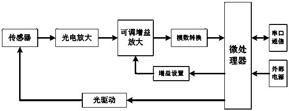
[0009] like image 3 As shown, in the prior art, a first-stage photoelectric amplifier circuit is usually used. The photoelectric amplifier circuit is followed by an adjustable gain amplifier circuit, and combined with light source drive adjustment to realize the adaptation of the measurement system to the medium to be measured and the signal strength. Photoelectric amplifier circuit, so that the joint debugging of the light source drive circuit, the first-stage amplifier circuit and the adjustable gain amplifier circuit is a serial process, so the adjustment speed is slow, and the adaptable range is not wide enough, and it is prone to overshoot, that is, for a small number of Extreme measurement conditions can exceed the regulation range of the circuit

Method used


Image

  • Blood oxygen measuring device and system as well as blood oxygen signal detection method
  • Blood oxygen measuring device and system as well as blood oxygen signal detection method
  • Blood oxygen measuring device and system as well as blood oxygen signal detection method

Examples


Embodiment Construction

[0027] Embodiments of the present invention will be described in further detail below in conjunction with the accompanying drawings.

[0028] Such as figure 1 In a specific embodiment of the blood oxygen measurement device and system shown, the main control module is a microprocessor, and the main control module controls the light drive circuit, the bias setting circuit, the first selection control circuit of the photoelectric amplification channel and the secondary amplification circuit respectively. Channel selection control circuit.

[0029] Such as figure 1 As shown, the first selection control circuit of the photoelectric amplification channel is arranged between the sensor and the four photoelectric amplification circuits, and is used to select the photoelectric amplification channel in the four photoelectric amplification circuits; one end of the first selection control circuit of the photoelectric amplification channel and the sensor Connect to obtain the original ...


PUM


Abstract

The invention discloses a blood oxygen measuring device and system as well as a blood oxygen signal detection method. At least four photoamplifier circuits are provided, the four photoamplifier circuits are sequentially and respectively connected by a master control module to obtain four measurement signals, and the photoamplifier circuit of which the measurement signal firstly reaches the range from 700 mv to 900 mv is selected as a photoamplifier circuit for subsequent measurement. When the four measurement signals do not range from 700 mv to 900 mv, the output power of a light source is regulated to be N or 1 / N times as much as that of the previous output power until the measurement signal of at least one photoamplifier circuit ranges from 700 mv to 900 mv. Due to the adoption of a multipath photoelectric amplification and optically-driven joint regulation method and the setting of the amplification factor and polarization of a post-stage amplification circuit on the basis, the circuits rapidly adapt to an external measurement condition, so that an adaption process between an optical signal and the external measurement condition is greatly shortened, furthermore, the rapid bloodoxygen measurement is realized, and particularly, the initial blood oxygen response time is far superior to that in the prior art.

Description

technical field [0001] The invention relates to the technical field of medical equipment, in particular to a blood oxygen measurement device, a system and a blood oxygen signal detection method for pulse blood oxygen measurement using red light and infrared light. Background technique [0002] Blood oxygen saturation (SpO2) is the percentage of the capacity of oxygen-bound oxyhemoglobin (HbO2) in the blood to the total hemoglobin (Hb, hemoglobin) capacity that can be combined, that is, the concentration of blood oxygen in the blood, which is the respiratory cycle important physiological parameters. Monitoring of arterial oxygen saturation (SaO2) allows estimation of lung oxygenation and hemoglobin oxygen-carrying capacity. The blood oxygen saturation of normal human arterial blood is 98%, and that of venous blood is 75%. [0003] A pulse oximeter is a medical device that measures the amount of oxygen in a patient's arterial blood. Pulse oximeters provide a non-invasive wa...

Claims


Application Information

Patent Timeline
Patent Type & Authority Applications(China)
IPC IPC(8): A61B5/1455
CPCA61B5/14551A61B5/14557
Inventor 叶继伦刘春生王凡蒋芸
Owner SHENZHEN WEITUOLI MEDICAL ELECTRONICS
Learn More