
Power decoupling control method and system for virtual synchronous generator based on voltage feedforward compensation

A technology of generator power and virtual synchronization, applied in the direction of single-grid parallel feeding arrangement, etc., can solve the problems affecting the output power control accuracy, dynamic response system stability, reducing inverter capacity requirements, etc., to alleviate the reactive power shortage , the effect of improving coupling problems and reducing capacity requirements

Active Publication Date: 2019-12-10
HUAZHONG UNIV OF SCI & TECH
View PDF3 Cites 12 Cited by
  • Summary
  • Abstract
  • Description
  • Claims
  • Application Information

AI Technical Summary

Problems solved by technology

[0005] Aiming at the problem that the power coupling of virtual synchronous generator will affect the control accuracy, dynamic response and system stability of its output power in the prior art, a power decoupling control method of virtual synchronous generator based on voltage feed-forward compensation is proposed and The system significantly improves the coupling problem between the active power loop and the reactive power loop, alleviates the reactive power shortage of the grid, and reduces the capacity demand for the inverter

Method used


Image

  • Power decoupling control method and system for virtual synchronous generator based on voltage feedforward compensation
  • Power decoupling control method and system for virtual synchronous generator based on voltage feedforward compensation
  • Power decoupling control method and system for virtual synchronous generator based on voltage feedforward compensation

Examples


Embodiment Construction

[0046] In order to make the objectives, technical solutions and advantages of the present invention clearer, the following further describes the present invention in detail with reference to the accompanying drawings and embodiments. It should be understood that the specific embodiments described herein are only used to explain the present invention, but not to limit the present invention.

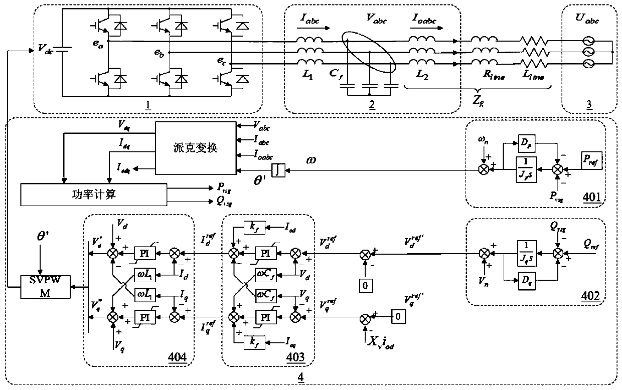
[0047] First, the topology of the virtual synchronous generator is explained. See figure 1 , The topology includes three-phase voltage source inverter 1, LCL filter 2, grid 3 and virtual synchronous generator controller 4. The virtual synchronous generator controller 4 includes active power loop 401, reactive power loop 402, voltage Control loop 403 and current control loop 404. Where V dc It is the DC side voltage source of the inverter, the machine side inductance L 1 And filter capacitor C f And grid-side inductance L 2 Form the output filter of the inverter, R line Is the grid line re...


PUM


Abstract

The invention belongs to the technical field of power electronic device control, and relates to a power decoupling control method and system for a virtual synchronous generator based on voltage feedforward compensation. The method comprises the steps of firstly, acquiring output power Pvsg and Qvsg of the virtual synchronous generator; giving a reactive power reference value Qref, subtracting thereactive power Qvsg output by the virtual synchronous generator from the reactive power reference value Qref to obtain d-axis initial reference voltage V<d><ref'> through an inertia equation of a reactive power loop, setting the q-axis initial reference voltage V<q><ref'> to be 0 at the same time, then presetting voltage feedforward equivalent inductive reactance Xv, and generating feedforward voltage Xviod; and obtaining a voltage control loop reference instruction V<d><ref> according to the d-axis initial reference voltage V<d><ref'>, subtracting the feedforward voltage Xviod from the q-axisinitial reference voltage V<q><ref'> to obtain a voltage control loop reference instruction V<q><ref>, and finally generating an SVPWM control instruction through a voltage control loop and a currentcontrol loop according to the voltage control loop reference instruction. According to the invention, the coupling problem between active power output and reactive power output is significantly improved, and the capacity requirement of the inverter is reduced.

Description

Technical field [0001] The invention belongs to the technical field of power electronic device control, and more specifically, relates to a virtual synchronous generator power decoupling control method and system based on voltage feedforward compensation. Background technique [0002] With the gradual depletion of fossil energy, distributed energy such as wind and solar energy has received extensive attention. In recent years, large-scale new energy power stations with power electronic converters as the interface have been established in China, which has reduced the inertia of the power system and adversely affected the stable operation of the power grid. Traditional synchronous motors have the advantage of being naturally friendly to the power grid, and their moment of inertia and damping characteristics play an important role in maintaining the stable operation of the power grid. Based on this, scholars put forward the concept of virtual synchronous generator, which can realiz...

Claims


Application Information

Patent Timeline
IPC IPC(8): H02J3/48H02J3/50H02J3/38
CPCH02J3/48H02J3/50
Inventor 邹旭东蒋秉辰温提亮江伟斌吴伟标郭祥姜聪聪彭敏强郭超
Owner HUAZHONG UNIV OF SCI & TECH
Learn More