Flue gas desulfurization tower and flue gas dust removal, desulfurization and wastewater treatment process

A desulfurization tower and flue gas technology, used in desulfurization and wastewater treatment processes, flue gas desulfurization towers and flue gas dust removal fields, can solve the problem that the space of catalytic devices and coal-fired boilers cannot be upgraded, covers a large area, and restricts dust removal and desulfurization devices. Construction and upgrading issues

Active Publication Date: 2019-12-13
CHINA PETROLEUM & CHEM CORP +1
View PDF22 Cites 3 Cited by
  • Summary
  • Abstract
  • Description
  • Claims
  • Application Information

AI Technical Summary

Problems solved by technology

The above-mentioned wet desulfurization technology includes flue gas desulfurization, desulfurization wastewater oxidation treatment or regeneration unit. The process is long, there are many equipments, and the floor area is large, which seriously restricts the construction and upgrad

Method used


Image

  • Flue gas desulfurization tower and flue gas dust removal, desulfurization and wastewater treatment process
  • Flue gas desulfurization tower and flue gas dust removal, desulfurization and wastewater treatment process
  • Flue gas desulfurization tower and flue gas dust removal, desulfurization and wastewater treatment process

Examples


Embodiment 1

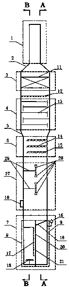
[0070] A flue gas dedusting and desulfurization tower, from top to bottom are the flue gas discharge area 1, the demisting area 3, the tower area 4, the spray area 6, the rapid cooling and cooling area 27 and the waste water treatment area 7, and the flue gas discharge area 1 It is connected with the defogging area 3 through the cone-shaped diameter 2, the tower area 4 is below the demisting area 3, the tower area 4 is connected with the spraying area 6 through the inverted cone-shaped diameter 5, and the lower part of the spraying area 6 is quenching and cooling Zone 27, below the rapid cooling and cooling zone 27 is the waste water treatment zone 7. The chimney 1 has a diameter of 3m, the tower upper shell 3 has a diameter of 9m, and the tower lower shell 7 has a diameter of 6m.

[0071] The demister described in CN201621043983.8 is set in the demister area 3, the liquid distributor 12 is arranged under the demist area 3, the tray area 4 is arranged under the liquid distribu...

Embodiment 2

[0079] The flue gas volume of an enterprise is 180000Nm 3 / h, the flue gas temperature is 165°C, the pressure is 3.5kPa, where SO 2 The concentration is 850mg / Nm 3 , Dust concentration is 210mg / Nm 3 , using the flue gas desulfurization tower of the present invention, the clean water flow rate in the quenching cooling zone is 60 m 3 / h. SO in exhaust flue gas 2 The content is measured by German Testo flue gas analyzer (model Testo-350). The dust content is measured according to GB / T 16157-1996 "Sampling Method for Particulate Matter and Gaseous Pollutants in Exhaust from Stationary Pollution Sources". The gas is filtered, dissolved in water, and the salt content is measured and calculated according to HJ / T51-1999 "Gravimetric Method for Determination of Total Salt in Water Quality". After measurement and calculation, the temperature of the flue gas entering the chimney is 53 ° C, SO 2 The concentration is 12.8mg / Nm 3 , Dust content is 8.5mg / Nm 3 , soluble salt content is...

Embodiment 3

[0081] Close the valve on the clean water pipeline entering the quenching and cooling zone, and adjust the flow of clean water to 0m 3 / h, all the other are the same as in Example 1, the flue gas temperature entering the chimney is 54 ℃, SO 2 The content is 13.3mg / Nm 3 , Dust content is 14.8mg / Nm 3 , soluble salt content is 8.2mg / Nm 3 .


PUM

PropertyMeasurementUnit
Diameteraaaaaaaaaa
Diameteraaaaaaaaaa
Diameteraaaaaaaaaa

Abstract

The invention discloses a flue gas desulfurization tower and a flue gas dust removal, desulfurization and wastewater treatment process. The flue gas desulfurization tower sequentially comprises a fluegas discharge area, a demisting area, a tray area, a spraying area, a quenching area and a wastewater treatment area from top to bottom; the flue gas discharge area is connected with the demisting area through a cone in a reducing manner, and the tray area is connected with the spraying area through an inverted cone in a reducing manner; the wastewater treatment area is divided into an oxidationflocculation area and a circulating clear liquid area through a vertical partition plate I in the center of the wastewater treatment area; the top of the circulating clear liquid area is completely isolated from the oxidation flocculation area and the spraying area by a partition plate II; and the vertical partition plate I is provided with a filter medium. Flue gas dust removal, desulfurization,desalting and wastewater treatment are carried out in one tower, so that the occupied area is greatly reduced, and the cost required by construction and transformation of the device and the operatingcost of the device are remarkably reduced.

Description

technical field [0001] The invention belongs to the field of industrial waste gas purification, and relates to a flue gas desulfurization tower and flue gas dust removal, desulfurization and waste water treatment processes. Background technique [0002] Sulfur dioxide and dust are contained in the flue gas of coal-fired boilers and the regenerated flue gas of catalytic cracking catalysts. Sulfur dioxide and dust are the main components of air pollutants. Sulfur dioxide is the main cause of acid rain, and dust with smaller particle sizes is the smog One of the culprits. [0003] Environmental pollution is becoming more and more serious, smog incidents occur frequently, and the country pays more and more attention to environmental protection. In recent years, a series of environmental protection laws and regulations, national standards, and management methods have been issued. GB 13223-2011 "Emission Standard of Air Pollutants for Thermal Power Plants" stipulates: coal-fired ...

Claims


Application Information

Patent Timeline
IPC IPC(8): B01D53/50B01D53/80B01D53/96B01D47/12C02F9/04C02F103/18
CPCB01D47/12B01D53/504B01D53/96C02F1/001C02F1/5236C02F1/66C02F1/722C02F9/00C02F2103/18
Inventor 宫超李磊李欣刘忠生金平王海波
Owner CHINA PETROLEUM & CHEM CORP
Why Eureka
Try Eureka