Long-working distance inner hole cladding optical system capable of outputting rectangular light spot

A technology with working distance and rectangular light spot, applied in optics, optical components, metal material coating process, etc., can solve the problem that cladding cannot be effectively processed, and achieves improved cladding efficiency, utilization rate, and spot energy homogenization. Effect

Pending Publication Date: 2019-12-13
XIAN BESAME LASER TECH CO LTD
View PDF0 Cites 0 Cited by
  • Summary
  • Abstract
  • Description
  • Claims
  • Application Information

AI Technical Summary

Problems solved by technology

[0007] The purpose of the present invention is to overcome the technical problem that the existing laser cladding equipment cannot effectively process the cladding of the inner hole surface of hole parts, and provide a long working distance inner hole cladding optical system that outputs a rectangular spot

Method used


Image

  • Long-working distance inner hole cladding optical system capable of outputting rectangular light spot
  • Long-working distance inner hole cladding optical system capable of outputting rectangular light spot

Examples


Embodiment 1

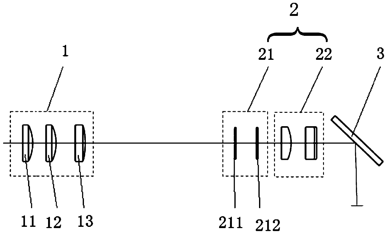
[0034] Such as figure 1 As shown, a long working distance inner hole cladding optical system that outputs a rectangular spot, including a housing, a beam transformation and transmission group 1, a beam energy transformation and shaping subsystem 2, and a beam direction optimization group arranged in sequence along the beam direction 3. The housing is not shown in the figure; the beam conversion and transmission group 1, the beam energy conversion and shaping subsystem 2, and the beam direction optimization group 3 are all set in the housing; Optical hole; Beam conversion and transmission group 1 is composed of 1 to 6 lenses, which is used to adjust and transform the beam output from the optical fiber to the spot size and shape, and can carry out long-distance transmission; Beam energy conversion and shaping subsystem 2 includes beam energy conversion group 21 and beam shaping group 22;

[0035] The beam energy transformation group 21 is composed of 1 to 4 array lenses, which ...

Embodiment 2

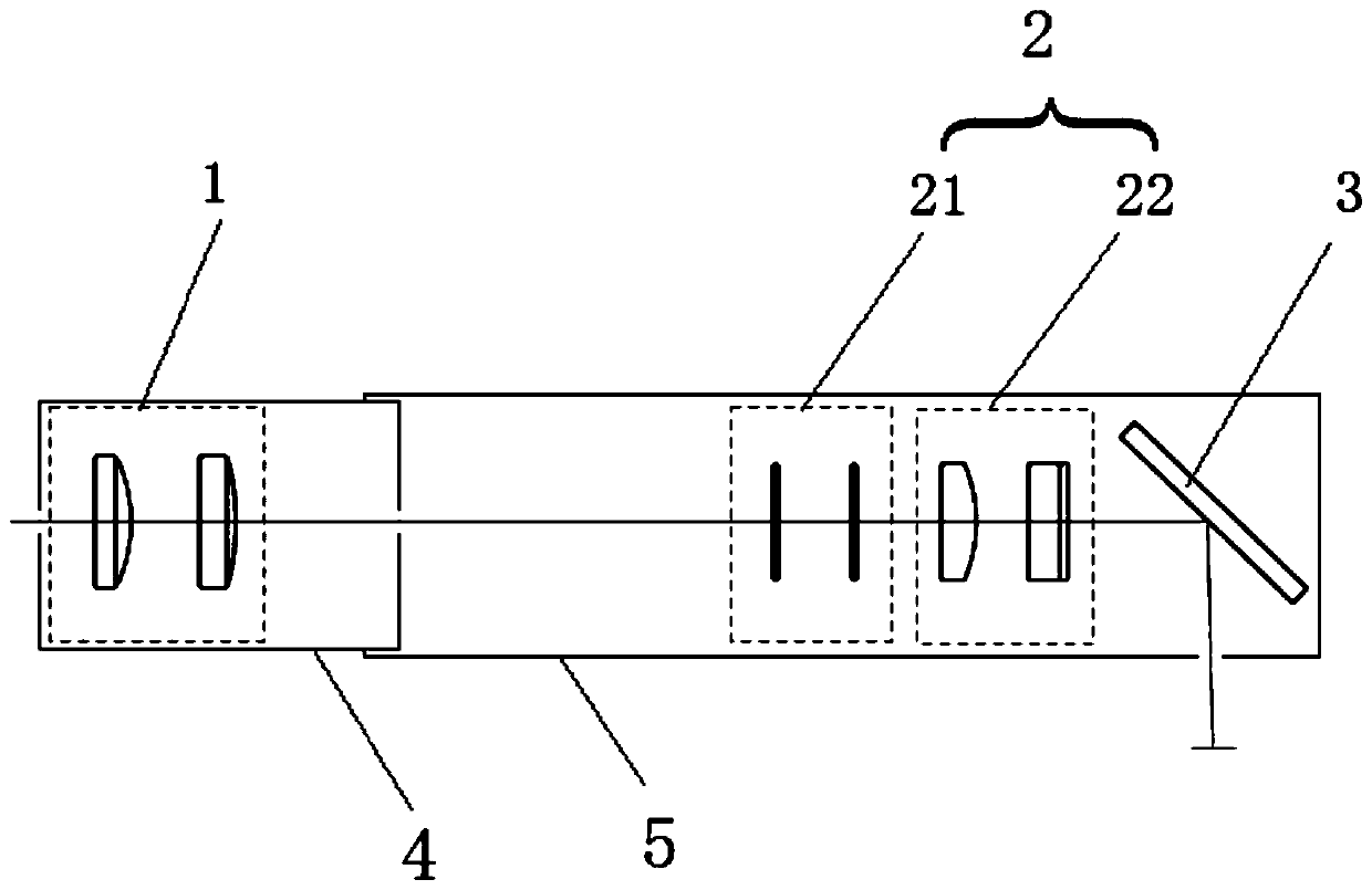
[0042] Such as figure 2 As shown, the housing is improved on the basis of Embodiment 1. The housing includes a first housing 4 and a second housing 5 arranged coaxially in sequence, and the first housing 4 can be moved relative to the second housing 5 in the axial direction. Do reciprocating movement; among them, the beam conversion transmission group 1 is arranged on the first housing 4, the beam energy conversion and shaping subsystem 2, and the beam direction optimization group 3 are arranged on the second housing 5, and the beam conversion group passes through Adjusting the distance between the lenses and cooperating with the movement between the first housing and the second housing can ensure that the light beam is transmitted within 0.3-6m.

[0043] Both ends of the first housing 4 are provided with light holes for light beams to pass through, and the first housing 4 can also be a cylindrical structure with both ends open; correspondingly, the second housing 5 can be a ...


PUM


Abstract

The invention provides a long-working distance inner hole cladding optical system capable of outputting a rectangular light spot. By the long-working distance inner hole cladding optical system, the problem that inner hole surface cladding of a hole part cannot be effectively processed by existing laser cladding equipment is solved. The system comprises a shell, a light beam conversion transmission group, a light beam energy conversion and shaping sub-system and a light beam steering optimization group which are sequentially arranged in the shell along a light beam direction, a light through hole is formed in the shell, the light beam conversion transmission group comprises 1-6 lenses and is used for performing adjustment and conversion on a cross section size and a light spot shape of a fiber output light beam, and remote-distance transmission can be achieved, the light beam energy conversion and shaping sub-system comprises a light beam energy conversion group and a light beam shaping group, the light beam energy conversion group comprises 1-4 array lens and is used for adjusting and converting transmission light beam energy distribution, the light beam shaping group comprises 1-4 conversion lens and is used for shaping and converting the light beam shape and converting the transmission light beam to the rectangular light spot, and the light beam steering optimization group is used for changing a light beam propagation direction and optimizing light beam energy distribution.

Description

technical field [0001] The invention relates to an inner hole cladding optical system, in particular to an inner hole cladding optical system with a long working distance outputting a rectangular light spot. Background technique [0002] Laser cladding technology refers to the surface additive manufacturing technology that melts the coating powder and the surface material of the substrate at the same time through the irradiation of high-power laser, and solidifies on the joint surface in a very short time to form a metallurgical bond. Laser cladding technology can increase the hardness of the substrate surface and significantly improve its wear resistance and corrosion resistance. Especially for parts that fail due to surface damage, laser cladding technology can be directly repaired, which can not only meet the surface characteristics requirements of the repaired parts, but also greatly save costs. It has been widely used in aerospace, electric power, coal and other industr...

Claims


Application Information

Patent Timeline
IPC IPC(8): G02B27/09C23C24/10
CPCG02B27/0927G02B27/0955G02B27/0972G02B27/0977G02B27/0966C23C24/10
Inventor 王晓飚高毅李欣
Owner XIAN BESAME LASER TECH CO LTD
Why Eureka
Try Eureka