
Method for suppressing specific harmonic waves of current source converter under extremely low switching frequency

A technology of switching frequency and specific harmonics, which is applied in the field of power quality management of grid-connected converters, can solve the problems of exponential growth of memory, inability to control harmonic components at the same time, and no adjustable degree of freedom, etc., to achieve the effect of improving power quality

Active Publication Date: 2019-12-13
TIANJIN UNIV
View PDF2 Cites 6 Cited by
  • Summary
  • Abstract
  • Description
  • Claims
  • Application Information

AI Technical Summary

Problems solved by technology

However, since the switching angle of specific harmonic cancellation modulation needs to be calculated offline, although the switching angles with different harmonic content can be calculated in advance and stored in the controller, if you want to control multiple harmonic components at the same time, it will lead to Exponential increase in required memory
According to the memory size of the existing controller, the asymmetric specific harmonic elimination method can only control a specific harmonic component, and cannot control more than two harmonic components at the same time
However, since the cut-off frequency of the AC side filter of a high-power current source converter is generally 200-350 Hz, the 5th and 7th harmonics in the line current have the risk of being amplified, and it is still impossible to compensate only a specific harmonic component. Meet the requirements in the actual system
[0004] In addition, the proposal of the bypass pulse injection method also solves the inherent problem that the traditional specific harmonic cancellation modulation method has no adjustable degree of freedom from another perspective.
However, based on the current existing technology, the degree of freedom added by the bypass pulse injection method is only used for DC current control [2] or parallel current source current sharing control [3], and is not used to compensate specific harmonics

Method used


Image

  • Method for suppressing specific harmonic waves of current source converter under extremely low switching frequency
  • Method for suppressing specific harmonic waves of current source converter under extremely low switching frequency
  • Method for suppressing specific harmonic waves of current source converter under extremely low switching frequency

Examples


Embodiment approach

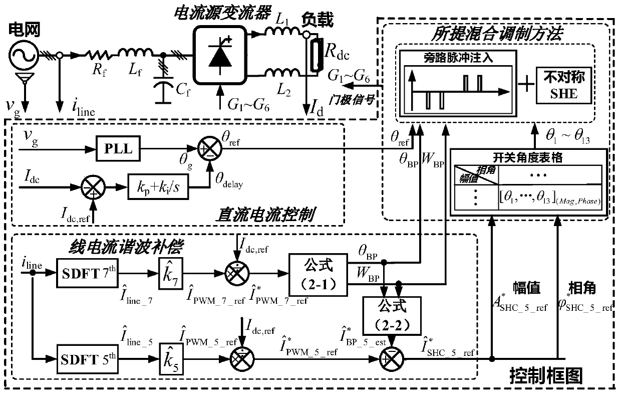
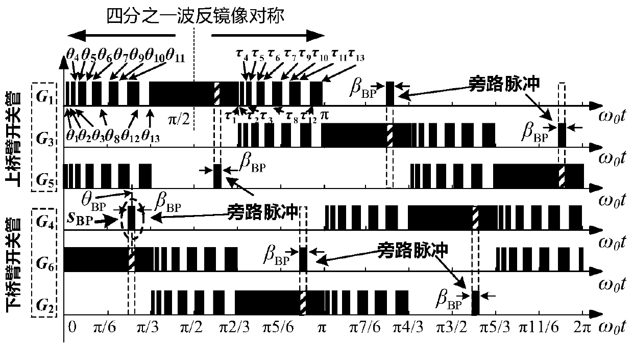
[0042] The hybrid modulation strategy of bypass pulse injection and asymmetric specific harmonic elimination in step (4) specifically includes the following steps:

[0043] a) The reference of the 7th harmonic component of the output PWM current after punit By calculation, the width of the bypass pulse β BP and position θ BP :

[0044]

[0045] in, respectively amplitude and phase angle.

[0046] b) by the width of the bypass pulse β BP and position θ BP Calculate the estimated value of the bypass pulse spurious 5th harmonic current after punit the magnitude of and phase angle

[0047]

[0048] c) The resulting estimated value The 5th harmonic component of the output PWM current after p.u. summed to get the 5th harmonic reference of the input asymmetry specific harmonic cancellation modulation

[0049] d) based on the magnitude of and phase angle Select the corresponding asymmetry-specific harmonic cancellation modulation switching angle θ 1...


PUM


Abstract

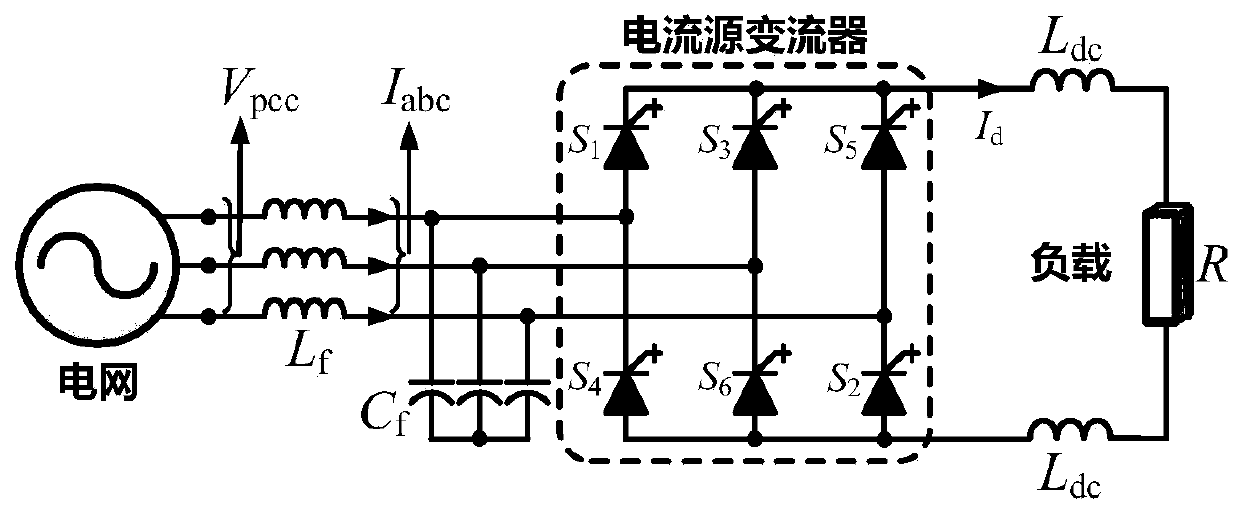
The invention discloses a method for suppressing specific harmonic waves of a current source converter under an extremely low switching frequency, which is characterized in that a three-phase currentsource type grid-connected rectifier topological structure is adopted, 5-order and 7-order harmonic components in output PWM current are actively controlled by a novel hybrid modulation method combining asymmetric specific harmonic elimination and bypass pulse injection, and active compensation is carried out on the 5-order and 7-order harmonic components in line current. The control strategy enables the high-power current source converter to have the capability of simultaneously performing active compensation on the 5-order and 7-order harmonic components under the extremely low switching frequency, so that the low-order harmonics of the line current can be effectively reduced under the condition of the voltage distortion of a power grid, the line current electric energy quality of the system is greatly improved, and the safe and stable operation of the system is ensured.

Description

technical field [0001] The invention relates to power quality control of a grid-connected converter, in particular to a method for suppressing specific harmonics of a current source converter at an extremely low switching frequency. Background technique [0002] In recent years, with the increasingly prominent energy problems and the increasing requirements of industrial production processes, medium-voltage high-power converters have become a common technical solution in many industries such as electric power, metallurgy, and transportation as a means of energy conservation and emission reduction. According to the difference in the energy storage link of the DC side, the converter is divided into a voltage source converter (VSC) and a current source converter (CSC). Although in the current medium-voltage high-power transmission system, VSC occupies a dominant position due to its high efficiency and the advantages of power switching devices, CSC, as one of the solutions for h...

Claims


Application Information

Patent Timeline
IPC IPC(8): H02M7/162H02M1/12H02M1/14
CPCH02M7/1626H02M1/126H02M1/14
Inventor 张昌浩何晋伟
Owner TIANJIN UNIV
Learn More