
Single regenerative heating furnace system for reducing NOx emissions

A heating furnace and single heat storage technology, which is applied in the direction of lighting and heating equipment, furnaces, furnace components, etc., can solve the problems of unfavorable control of atmosphere, increase of emission concentration, and unstable flame organization, so as to improve flame stability and reduce secondary Secondary combustion occurs and the effect of reducing combustible components

Inactive Publication Date: 2019-12-17
ZHANGJIAGANG HONGCHANG STEEL PLATE CO LTD +2
View PDF5 Cites 1 Cited by
  • Summary
  • Abstract
  • Description
  • Claims
  • Application Information

AI Technical Summary

Problems solved by technology

[0002] At present, regenerative combustion technology is commonly used in steel rolling heating furnaces. The furnace temperature is usually between 1100 and 1350°C, which belongs to high-temperature heating furnaces. At the same time, with regenerative combustion technology, the gas preheating temperature can reach 1000°C. High preheating temperature can easily cause NO x generation
In addition, with regenerative combustion technology, air and fuel enter the furnace from their respective nozzles, the flame is in a diffuse combustion state, and the flame structure is unstable, which is not conducive to controlling the atmosphere. When the oxygen content in a local area is too high, it will also increase NO x emission concentration

Method used


Image

  • Single regenerative heating furnace system for reducing NOx emissions
  • Single regenerative heating furnace system for reducing NOx emissions
  • Single regenerative heating furnace system for reducing NOx emissions

Examples


Embodiment Construction

[0024] The technical solutions in the embodiments of the present invention will be described in detail below in conjunction with the accompanying drawings in the embodiments of the present invention. Obviously, the described embodiments are only some of the embodiments of the present invention, not all of them. Based on the embodiments of the present invention, all other embodiments obtained by persons of ordinary skill in the art without making creative efforts belong to the protection scope of the present invention.

[0025] In the description of the present invention, it should be noted that the terms "center", "upper", "lower", "left", "right", "vertical", "horizontal", "inner", "outer" etc. The indicated orientation or positional relationship is based on the orientation or positional relationship shown in the drawings, and is only for the convenience of describing the present invention and simplifying the description, rather than indicating or implying that the referred de...


PUM


Abstract

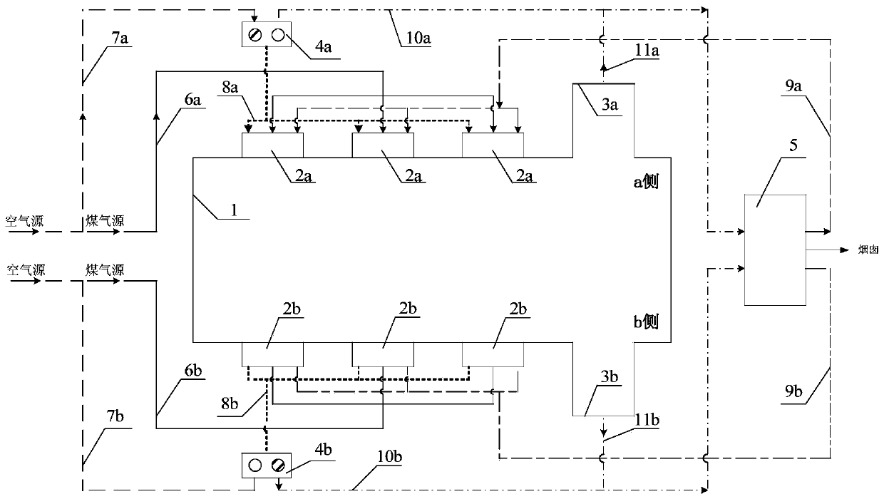
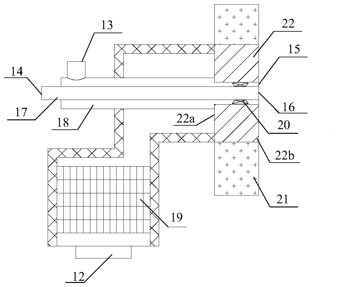
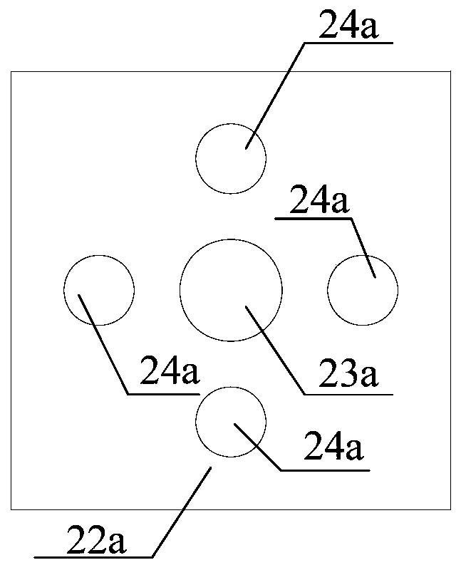
The invention discloses a single regenerative heating furnace system for reducing NOx emissions. The two sides of a furnace wall of a heating furnace are symmetrically provided with a plurality of burners, coal gas spray pipes of the multiple burners in the same side are in communication to one same coal gas pipe, air spraying openings of the multiple burners in the same side are in communicationto one same air and flue gas pipe, the air and flue gas pipe is connected to an air pipe and a flue gas recovery pipe on the side through a reversing valve, and the flue gas recovery pipe is in communication to an auxiliary flue on the side and is led into a flue gas gathering chamber; and the auxiliary flues are arranged on the two sides of the furnace wall of the heating furnace, the flue gas gathering chamber is provided with two circulating flue gas pipes, each circulating flue gas pipe is in communication to a plurality of circulating flue gas spray pipes on the same side, and each coal gas spray pipe is installed at the center of the corresponding circulating flue gas spray pipe. The single regenerative heating furnace system has the advantages that emission reduction of NOx of the heating furnace is effectively achieved, and the intensity of combustion and the stability of flames are improved.

Description

technical field [0001] The application relates to the field of regenerative heating furnace equipment and industrial gas pollutant emission control, in particular to a single regenerative heating furnace system for reducing NOx emissions. Background technique [0002] At present, regenerative combustion technology is commonly used in steel rolling heating furnaces. The furnace temperature is usually between 1100 and 1350°C, which belongs to high-temperature heating furnaces. At the same time, with regenerative combustion technology, the gas preheating temperature can reach 1000°C. High preheating temperature can easily cause NO x generation. In addition, with regenerative combustion technology, air and fuel enter the furnace from their respective nozzles, the flame is in a diffuse combustion state, and the flame structure is unstable, which is not conducive to controlling the atmosphere. When the oxygen content in a local area is too high, it will also increase NO x emissi...

Claims


Application Information

Patent Timeline
IPC IPC(8): F27D99/00F23C9/08
CPCF23C9/08F27D99/0033F27D2099/0056
Inventor 杨丽琴丁美良孙林曲锦波
Owner ZHANGJIAGANG HONGCHANG STEEL PLATE CO LTD
Learn More