Flue gas adsorption catalytic reaction high-precision desulfurization method

A technology for adsorption catalysis and flue gas, applied in chemical instruments and methods, separation methods, gas treatment, etc., can solve the problems of technical operation cost, high investment, limited adsorption capacity of adsorbent, and difficulty in realizing continuous production, etc. Adsorption catalytic reaction function, complete reaction, and the effect of improving the pass rate

Inactive Publication Date: 2019-12-20
宋强
View PDF2 Cites 4 Cited by
  • Summary
  • Abstract
  • Description
  • Claims
  • Application Information

AI Technical Summary

Problems solved by technology

[0002] With the improvement of environmental protection requirements, the emission index of sulfur dioxide, flue gas desulfurization, sulfur trioxide, fluorine chlorine gas (HF, HCl, Cl 2 etc.) It is difficult to meet the emission targets, and the operating cost and investment of technologies that can meet the emission targets are high
[0005] The disadvantage of

Method used


Image

  • Flue gas adsorption catalytic reaction high-precision desulfurization method
  • Flue gas adsorption catalytic reaction high-precision desulfurization method

Examples


Example Embodiment

[0034] Example one:

[0035] Follow the steps below to treat the above flue gas:

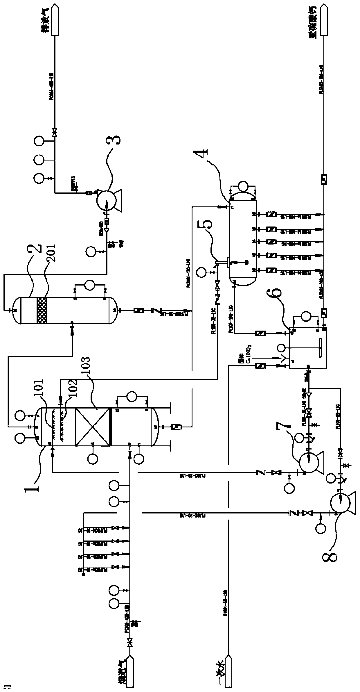
[0036] S1. The flue gas from the flue gas main pipe enters the flue gas pipe under the action of the induced draft fan 3. The flue gas flow rate is 3500m 3 / h. At the same time, the prepared alkaline spray water is pumped by the circulating cooling pump 8 to spray and cool the high-temperature flue gas in the flue gas pipeline, so as to cool the flue gas and complete the process of preliminary desulfurization and dust collection at the same time. It is measured that the flue gas temperature drops to 58°C before entering the desulfurization tower.

[0037] S2. After the flue gas is desuperheated, it enters the desulfurization tower, and the desulfurization tower is provided with an adsorption catalyst solid bed 103, and the adsorption catalyst filled with the adsorption catalyst solid bed 103 is based on pseudo-boehmite as the framework, aluminum magnesium silicon After roasting with acid salt as auxi...

Example Embodiment

[0043] Embodiment two:

[0044] Follow the steps below to treat the above flue gas:

[0045] S1. The flue gas from the flue gas main pipe enters the flue gas duct under the action of the induced draft fan 3. The flue gas flow rate is 8600m 3 / h. At the same time, the prepared alkaline spray water is pumped by the circulating cooling pump 8 to spray and cool the high-temperature flue gas in the flue gas pipeline, so as to cool the flue gas and complete the process of preliminary desulfurization and dust collection at the same time. It is measured that the flue gas temperature drops to 62°C before entering the desulfurization tower.

[0046] S2. After the flue gas is desuperheated, it enters the desulfurization tower, and the desulfurization tower is provided with an adsorption catalyst solid bed 103. The adsorption catalyst filled with the adsorption catalyst solid bed 103 is based on pseudo-boehmite as the framework, aluminum magnesium silicon After roasting with acid salt as auxil...

Example Embodiment

[0052] Example three:

[0053] Follow the steps below to treat the above flue gas:

[0054] S1. The flue gas from the flue gas main pipe enters the flue gas duct under the action of the induced draft fan 3, and the flue gas flow rate is 11200m 3 / h. At the same time, the prepared alkaline spray water is pumped by the circulating cooling pump 8 to spray and cool the high-temperature flue gas in the flue gas pipeline, so as to cool the flue gas and complete the process of preliminary desulfurization and dust collection at the same time. It is measured that the flue gas temperature drops to 57°C before entering the desulfurization tower.

[0055] S2. After the flue gas is desuperheated, it enters the desulfurization tower, and the desulfurization tower is provided with an adsorption catalyst solid bed 103. The adsorption catalyst filled with the adsorption catalyst solid bed 103 is based on pseudo-boehmite as the framework, aluminum magnesium silicon After roasting with acid salt as a...


PUM


Abstract

The invention discloses a flue gas adsorption catalytic reaction high-precision desulfurization method. The method comprises the following steps: A, pretreating flue gas and cooling; B, enabling the cooled flue gas to flow through an adsorption catalyst solid bed layer arranged in a desulfurization tower; then introducing alkali liquor into the desulfurization tower, and enabling the alkali liquorto flow through the adsorption catalyst solid bed layer, and carrying out a reaction with gas molecules adsorbed in the adsorption catalyst solid bed layer; C, carrying out solid-liquid separation onthe desulfurization solution to obtain a clear solution and a solid phase; D, allowing one part of the clear liquid to return to the desulfurization tower, swashing the adsorption catalyst solid bedlayer, and regenerating the adsorption catalyst solid bed layer; and supplementing an alkali into the other part of the clear liquid to adjust the pH, and then feeding the other part of the clear liquid into the desulfurization tower for recycling as alkali liquor; and E, carrying out gas-liquid separation to remove a liquid phase in the desulfurized flue gas, and thus obtaining exhaust gas. The method has the advantages that deep desulfurization of sulfur dioxide gas in the flue gas is realized, and the production process is simplified.

Description

technical field [0001] The invention relates to an industrial tail gas treatment method, in particular to a flue gas desulfurization method. Background technique [0002] With the improvement of environmental protection requirements, the emission index of sulfur dioxide, flue gas desulfurization, sulfur trioxide, fluorine chlorine gas (HF, HCl, Cl 2 etc.) It is difficult to reach the emission target, and the operating cost and investment of the technology that can reach the emission target are high. Due to the characteristics of flue gas flow, low pressure, complex composition, and corrosiveness, the existing technology basically uses chemical methods to remove sulfur dioxide (dual alkali method). [0003] In the specific operation process, the prepared lye is usually sprayed or sprayed into the desulfurization device to react with sulfur dioxide, sulfur trioxide and other gases to form CaSO 3 , CaSO 4 Wait for the corresponding solid phase to achieve desulfurization. Ho...

Claims


Application Information

Patent Timeline
IPC IPC(8): B01D53/86B01D53/50B01D53/96B01D53/78
CPCB01D53/502B01D53/504B01D53/8609B01D53/96B01D2258/0283
Inventor 宋强何麟
Owner 宋强
Why Eureka
Try Eureka