Method for welding battery tabs and busbar
A technology of a battery tab and a welding method, applied in the fields of welding and laser welding, can solve the problems of heavy weight, high processing cost of composite materials, poor welding strength, etc., and achieve the effects of simple structure, low cost, and reduced welding cost.
- Summary
- Abstract
- Description
- Claims
- Application Information
AI Technical Summary
Problems solved by technology
Method used
Image
Examples
Embodiment 1
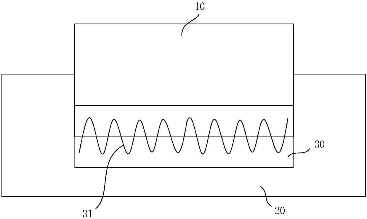
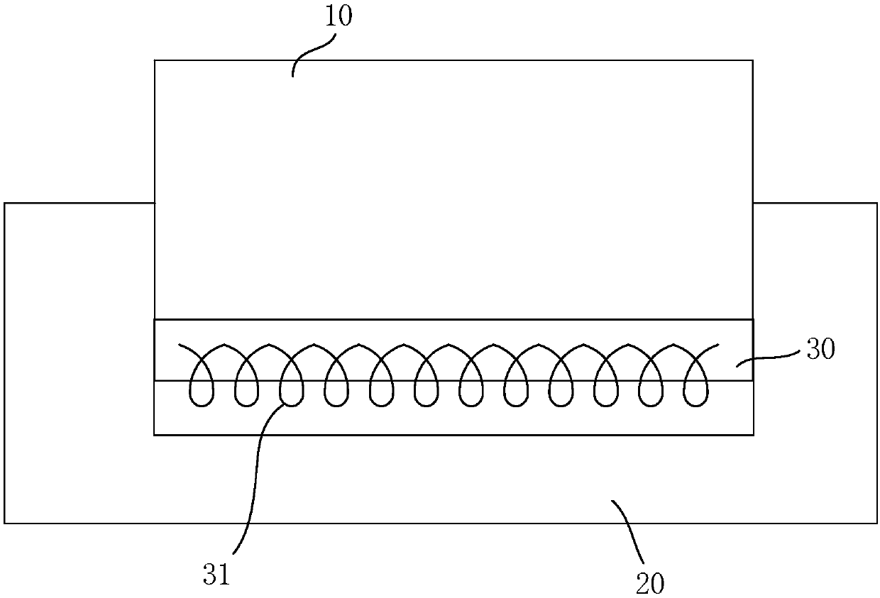
[0068]The battery tab 10 is bent and attached to the bus bar 20 , and the battery tab 10 and the bus bar 20 are connected as a whole through an outer frame support so that they are relatively fixed. The integrated battery tab 10 and the bus bar 20 are fixedly placed on a welding platform. The welding platform is moved so that the to-be-welded area 30 between the battery tab 10 and the bus bar 20 is placed at an initial welding position. The initial welding position makes one end of the region to be welded 30 correspond to the spot position of the laser beam of the laser welding device.
[0069] Wherein, the battery tab 10 is made of pure copper, and the bus bar 20 is made of pure aluminum.
[0070] A laser welding device is selected, wherein: the transmission fiber core diameter of the laser welding device is 10 μm, the optical amplification ratio of the laser beam is 1:1, and the output power of the laser is 500W.
[0071] The laser beam spot is welded along the curved traj...
Embodiment 2
[0073] The battery tab 10 is bent and attached to the bus bar 20 , and the battery tab 10 and the bus bar 20 are connected as a whole through an outer frame support so that they are relatively fixed. The integrated battery tab 10 and the bus bar 20 are fixedly placed on a welding platform. The welding platform is moved so that the to-be-welded area 30 between the battery tab 10 and the bus bar 20 is placed at an initial welding position. The initial welding position makes one end of the region to be welded 30 correspond to the spot position of the laser beam of the laser welding device.
[0074] Wherein, the battery tab 10 is made of pure aluminum, and the bus bar 20 is made of pure copper.
[0075] A laser welding device is selected, wherein: the transmission fiber core diameter of the laser welding device is 20 μm, the optical amplification ratio of the laser beam is 1:2, and the output power of the laser is 1200W.
[0076] The laser beam spot is welded along the curved tr...
Embodiment 3
[0078] The battery tab 10 is bent and attached to the bus bar 20 , and the battery tab 10 and the bus bar 20 are connected as a whole through an outer frame support so that they are relatively fixed. The integrated battery tab 10 and the bus bar 20 are fixedly placed on a welding platform. The welding platform is moved so that the to-be-welded area 30 between the battery tab 10 and the bus bar 20 is placed at an initial welding position. The initial welding position makes one end of the region to be welded 30 correspond to the spot position of the laser beam of the laser welding device.
[0079] Wherein, the battery tab 10 is made of pure copper, and the bus bar 20 is made of pure aluminum.
[0080] A laser welding device is selected, wherein: the transmission fiber core diameter of the laser welding device is 20 μm, the optical amplification ratio of the laser beam is 1:2, and the output power of the laser is 1500W.
[0081] The laser beam spot is welded along the curved tr...
PUM
| Property | Measurement | Unit |
|---|---|---|
| Diameter | aaaaa | aaaaa |
| Diameter | aaaaa | aaaaa |
| Thickness | aaaaa | aaaaa |
Abstract
Description
Claims
Application Information
 - R&D
- Intellectual Property
- Life Sciences
- Materials
- Tech Scout
- Unparalleled Data Quality
- Higher Quality Content
- 60% Fewer Hallucinations
Browse by: Latest US Patents, China's latest patents, Technical Efficacy Thesaurus, Application Domain, Technology Topic, Popular Technical Reports.
© 2025 PatSnap. All rights reserved.Legal|Privacy policy|Modern Slavery Act Transparency Statement|Sitemap|About US| Contact US: help@patsnap.com


