
Treatment method of oily sludge

A treatment method and sludge technology, applied in sludge treatment, water/sludge/sewage treatment, immiscible solvent sludge treatment, etc., can solve the problem of not being able to fully utilize the beneficial value of oily sludge and achieve full utilization Value, ease of control, effect of improving oil removal rate

Active Publication Date: 2019-12-20
CHINA UNIV OF PETROLEUM (EAST CHINA)
View PDF14 Cites 4 Cited by
  • Summary
  • Abstract
  • Description
  • Claims
  • Application Information

AI Technical Summary

Problems solved by technology

At present, the treatment methods of oily sludge at home and abroad mainly include incineration, pyrolysis, extraction, biological method, hot washing, etc. These treatment methods have certain advantages, but they also have limitations, and cannot make full use of oily sludge. Beneficial Value of Sludge

Method used


Image

  • Treatment method of oily sludge

Examples


Embodiment 1

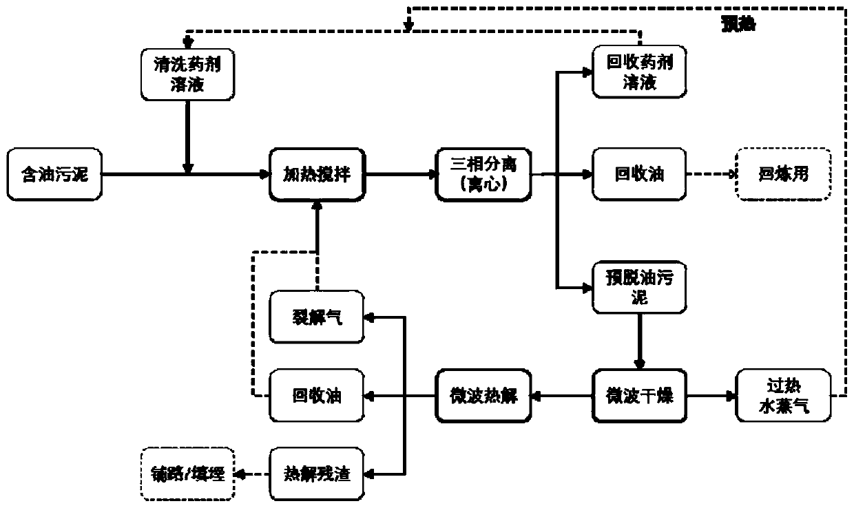
[0040] Such as figure 1 As shown, the treatment of oily sludge in an oilfield is as follows:

[0041] The water content of the oily sludge before treatment was 54wt%, the oil content was 26wt%, and the solid content was 20wt%.

[0042] The first step, the chemical heat detergent SDS, NP-10 and Na 2 SiO 3 Prepare a diluted solution of chemical heat cleaning agent with a concentration of 3wt% at a mass ratio of 1:1:1, mix the oily sludge and the chemical solution at a mass ratio of 1:4 and add them to the heating and stirring device.

[0043] The second step is to start heating, set the heating temperature to 80°C, and start stirring after the temperature reaches, set the stirring rate to 200r / min, and the stirring time to 50min, and carry out the chemical heat washing operation.

[0044] Step 3: After the chemical heat washing is completed, the material is taken out and sent to the centrifuge device. The centrifuged material will be layered, which is the upper layer of oil s...

Embodiment 2

[0047] The first step, the chemical heat detergent AEO-9, LAS and Na 2 SiO 3 Prepare a diluted solution of 3 wt% chemical heat cleaning agent at a mass ratio of 1:1:1, mix oily sludge (same source as in Example 1) and agent solution at a mass ratio of 1:4 and add to the heating and stirring device.

[0048] The second step is to start heating, set the heating temperature to 80°C, and start stirring after the temperature reaches, set the stirring rate to 200r / min, and the stirring time to 50min, and carry out the chemical heat washing operation.

[0049] Step 3: After the chemical heat washing is completed, the material is taken out and sent to the centrifuge device. The centrifuged material will be layered, which is the upper layer of oil slick, the middle layer of sewage, and the lower layer of sludge. Cutting and separation are carried out separately, the upper layer of slick oil and the middle layer of sewage are recovered, and the lower layer of sludge is treated as pre-o...


PUM


Abstract

The invention relates to a treatment method of oily sludge. The method comprises the following steps that a, the oily sludge is treated by hot washing with a chemical agent, then the heat washed sludge is stratified to form an upper layer oil phase, a middle layer water phase and lower layer sludge, and the upper layer oil phase, the middle layer water phase and lower layer sludge are collected respectively after separation; b, the lower layer sludge is subjected to two successive stages of microwave heat treatment; the first stage is heated for 150-220 DEG C, and an evaporated gas phase is collected in the first stage; and heating is continued to 580-600 DEG C for thermal decomposition in the second state, then generated non condensable gas and condensate are cooled and recovered, and finally, sludge residues after pyrolysis are collected. The treatment method of the oily sludge realizes the goal of reducing, harmlessness and resource treatment of the oily sludge.

Description

technical field [0001] The invention relates to the field of environmental protection, in particular to a treatment method for oily sludge. Background technique [0002] Oily sludge is a common pollutant in the petroleum industry, and a large amount of oily sludge may be produced in various links such as oil exploitation, gathering and transportation, and refining. Oily sludge is a pollutant mainly mixed with oil, sewage, sludge, etc. It usually contains a large amount of aged crude oil, oil extraction chemicals, salts, suspended solids, corrosion, and bacteria. Its composition is very complex, and direct discharge will Seriously endanger environmental safety. At present, oily sludge has been listed as hazardous solid waste (HW08) in the National List of Hazardous Wastes. [0003] With the continuous increase of oil exploitation, the output of oily sludge continues to increase every year. It is estimated that 1 ton of oily sludge is produced for every 500 tons of crude oi...

Claims


Application Information

Patent Timeline
IPC IPC(8): C02F11/00C02F11/131C02F11/10C10G1/04
CPCC02F11/00C02F11/002C02F11/131C02F11/10C10G1/04C10G2300/1003C10G2300/4006Y02W10/40
Inventor 侯影飞黄朝琦秦志文郭宁尚绪敏王刚温燕军
Owner CHINA UNIV OF PETROLEUM (EAST CHINA)
Learn More