
Laser shock gray cast iron component surface micro-texturing method

A surface micro-modeling and laser shock technology, applied in laser welding equipment, manufacturing tools, welding equipment, etc., can solve the problems of high cost and complex manufacturing process, improve wear resistance, good controllability, and avoid direct contact Effect

Inactive Publication Date: 2019-12-20
JIANGSU UNIV OF SCI & TECH
View PDF6 Cites 4 Cited by
  • Summary
  • Abstract
  • Description
  • Claims
  • Application Information

AI Technical Summary

Problems solved by technology

[0003] The improvement of wear performance of gray cast iron components mainly adopts optimized design of smelting process, material composition and other composite coating technologies such as thermal spraying and laser cladding. For example, the invention patent with application number 201721662689. Automobile brake discs, by coating the surface of gray cast iron to improve the wear resistance and high temperature resistance of the brake disc, the cost is high and the production process is complicated

Method used


Image

  • Laser shock gray cast iron component surface micro-texturing method
  • Laser shock gray cast iron component surface micro-texturing method
  • Laser shock gray cast iron component surface micro-texturing method

Examples


Embodiment

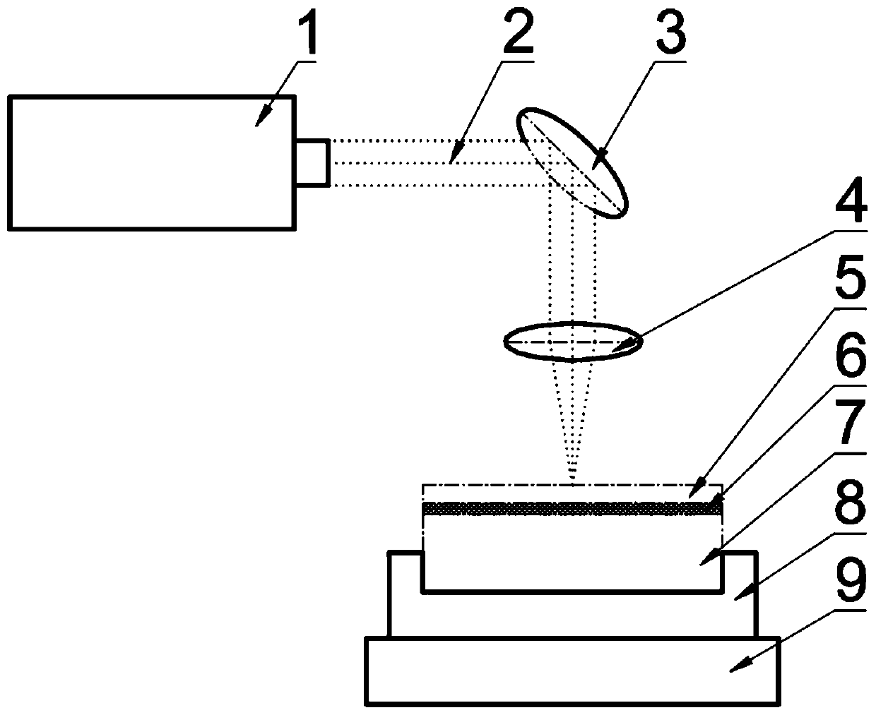
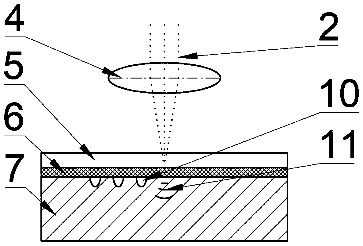
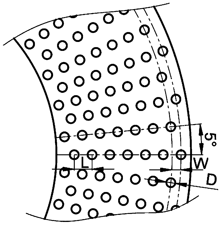
[0024] Such as figure 1 and figure 2 As shown, the gray cast iron component 7 is fixed on the numerical control workbench 9 through the clamp 8; the laser 1 emits the laser beam 2, and the horizontal optical path is converted into a longitudinal optical path through the reflector 3, and the focusing lens 4 passes through the constrained layer water 5, Focusing on the aluminum foil 6 of the energy absorbing layer, the shock wave 11 is transmitted to the interior of the gray cast iron component 7 for strengthening. The pressure of the shock wave 11 is much greater than the dynamic yield strength of the gray cast iron component 7, causing plastic deformation on the surface of the gray cast iron component 7 to form pits 10; By controlling the movement of the numerical control workbench 9 , the arrayed pits 10 are processed on the gray cast iron component 7 .

[0025] A kind of method (taking the brake disc as example) of laser shock gray cast iron component surface micromodeling...


PUM


Abstract

The invention provides a laser shock gray cast iron component surface micro-texturing method. The method is characterized in that a pulse laser is utilized to emit a laser beam, the laser beam is converted into a longitudinal light path through a reflecting mirror, and the longitudinal light path passes through a focusing lens, penetrates through constraint layer water, acts on an energy absorption layer aluminum foil and absorbs laser energy to rapidly generates plasma gasification to form a plasma cluster; and the plasma cluster is exploded to generate shock waves under the action of a constraint layer, the shock waves are transmitted to the interior of a gray cast iron material, pressure of the shock waves is far greater than dynamic yield strength of the gray cast iron, flake graphiteis dispersed and evolves into a spherical group shape, ferrite grains are refined and cut into smaller sub-grains, the surface of the gray cast iron generates plastic deformation and dislocation slipto form pits to relieve abrasive wear and adhesive wear, the wear surface is mainly Fe3O4, Fe2O3 and more cementite at high temperature, a discontinuous oxide film with a larger area is formed, directcontact of a friction pair is avoided, and wear resistance of the material is improved.

Description

technical field [0001] The invention relates to a method for laser shocking the surface micro-modeling of gray cast iron components, belonging to the technical field of laser processing. Background technique [0002] Gray cast iron is an important metal material in the modern manufacturing industry. It is widely used in friction pair components such as guide rails and brake discs because of its good self-lubricating properties, vibration damping and low-cost characteristics, but it will gradually wear out during use. , the main wear failure modes are adhesive wear and abrasive wear, and the high temperature wear surface is mainly iron oxide Fe 3 o 4 , Fe 2 o 3 , FeO and cementite, the friction surface changes from oxidative wear to adhesive wear, and then the wear is severe. [0003] To improve the wear performance of gray cast iron components, the optimization design of smelting process, material composition and other composite coating technologies such as thermal spray...

Claims


Application Information

Patent Timeline
IPC IPC(8): C21D10/00B23K26/046B23K26/064B23K26/70
CPCB23K26/046B23K26/0648B23K26/702C21D10/005
Inventor 樊玉杰姚康林周元凯苏宇刘志强夏晶
Owner JIANGSU UNIV OF SCI & TECH
Learn More