
Topping method in small coal pillar exploitation technology

A technology of small coal pillars and roof cutting, applied in ground mining, earthwork drilling, underground mining, etc., can solve problems such as large spacing, large crack deviation, and difficult roadway maintenance.

Active Publication Date: 2020-01-03
晋能控股煤业集团有限公司综采装备安装分公司
View PDF2 Cites 4 Cited by
  • Summary
  • Abstract
  • Description
  • Claims
  • Application Information

AI Technical Summary

Problems solved by technology

[0004] Regardless of "small coal pillar mining" or "coal pillarless mining" at the present stage, the roof cutting method mainly adopts "two-way energy-gathering blasting pre-splitting roof cutting". Before using this technology, various technical parameters must be determined, such as blast hole depth, Blast hole inclination and blast hole spacing, the determination of such parameters cannot be guaranteed to be applicable to various actual situations
[0005] The existing roof cutting method has the following deficiencies: (1) Blast hole spacing: If the spacing is too large, adjacent cracks cannot penetrate; if the spacing is too small, adjacent cracks will superimpose and the roof will be broken; Larger; the joint surface of the cracks is not smooth, and the resistance of the falling process of the roof in the later stage is large, which leads to serious rock mass fragmentation after the roadway is formed, and roadway maintenance is difficult; (4) Affected by various gas accidents, some mines have banned the use of blasting technology; (5) The cost of blasting pre-splitting is high, and the promotion for small mines is low

Method used

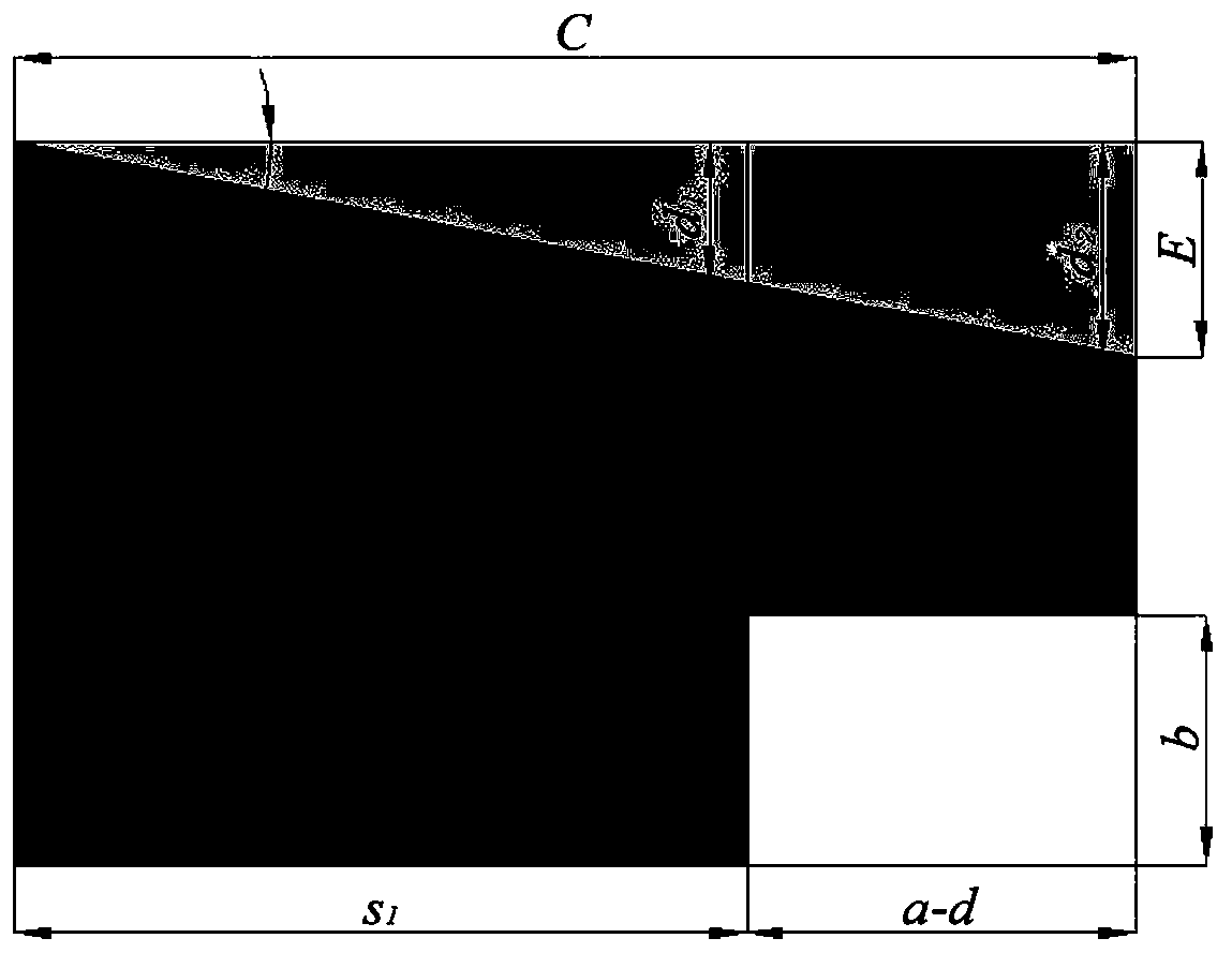
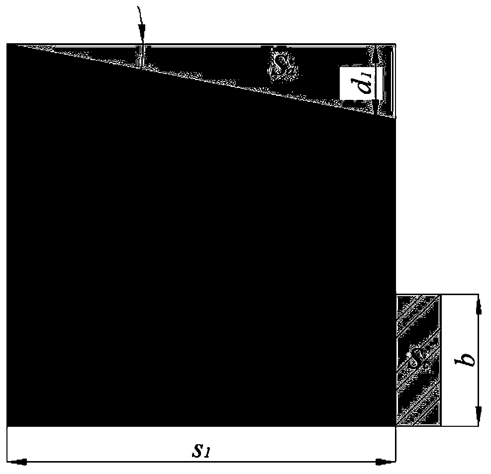
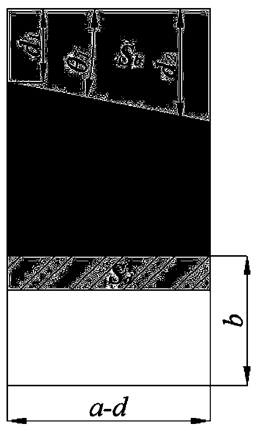

Image

  • Topping method in small coal pillar exploitation technology
  • Topping method in small coal pillar exploitation technology
  • Topping method in small coal pillar exploitation technology

Examples


specific example

[0213] 1. Engineering geological conditions

[0214] The 8311 working face in the third panel area of ​​Tashan Coal Mine is located in the west wing of the third panel area. The north of the working face is Lane 5311, the south is Lane 2311, the east is the lane of the west wing of the third panel area, and the west is the real coal area and Digginwan Jingtian Mountain 4 No. 8201 working face of coal seam is adjacent. The total thickness of the coal seam is 3.20-3.60m, with an average thickness of 3.40m. The occurrence of the coal seam changes little, with an inclination angle of 2°-4°, and the average coal seam inclination angle is 2°. Coal seam thickness factor is 3-4. Coal seams generally contain two layers of interlayers, the thickness of which is 0.10-0.30m, and the lithology of interlayers is gray-black mudstone, dark gray sandy mudstone, and kaolinite mudstone. According to the previous drilling histogram of Lane 2311 provided by the mine and the histogram obtained fr...


PUM


Abstract

The invention discloses a topping method in the small coal pillar exploitation technology. The topping method includes the following steps that firstly, the overlying strata performance and the occurrence state of a certain roadway top plate are systematically analyzed according to a certain roadway early borehole columnar section provided by a mine party and a columnar section acquired in recentborehole detection, and multiple cutting positions are selected out; analysis of each cutting position on the stability of the certain roadway top plate and the stability of an adjacent roadway coal pillar is analyzed through theoretical calculation of the stability of the roadway top plate and the stability of the roadway coal pillar, and the cutting position is determined; and after the cuttingposition is determined, a KLJ7 chain arm topping machine is used for carrying out cutting along a determined cutting path. The cutting position of the roadway top plate is scientifically determined, equipment is reasonably operated, by means of a mechanical topping manner, cut seams are straight, cutting surfaces are smooth, and the unloading effect is ideal. By means of the topping manner, the problems that during exploding pre-splitting, cracks are obstructed, the cracks are twisted, and the caving resistance of the top plate is large are solved.

Description

technical field [0001] The invention belongs to the technical field of roof cutting in coal mine mining, and in particular relates to a roof cutting method in small coal pillar mining technology. Background technique [0002] With the increase of mining intensity, coal resources are getting less and less, and the problems of low coal recovery rate, high mining ratio, and waste of resources caused by the traditional longwall mining method with two lanes on one side and coal pillars have become increasingly prominent. At the same time, engineering disasters such as roadway surrounding rock deformation, roof collapse, rock burst, coal and gas outburst caused by high stress concentration above the reserved coal pillars due to dynamic pressure are becoming more and more serious. The unreasonable setting causes the goaf pressure in the gob roadway and the advanced dynamic pressure of the working face to superimpose, and the mine pressure appears strongly. Therefore, adopting and ...

Claims


Application Information

Patent Timeline
IPC IPC(8): E21C41/18
CPCE21C41/18
Inventor 鲍永生宋银林荣飞胡锦东王自卫李海清刘建平刘阳阎宁
Owner 晋能控股煤业集团有限公司综采装备安装分公司
Learn More