
Capacity optimization configuration method for urban rail transit photovoltaic energy storage system

A technology for urban rail transit and capacity optimization configuration, applied in the direction of load balance in DC network, parallel operation of DC power supply, etc., can solve the cost and impact of immature energy storage technology, and the capacity optimization of urban rail photovoltaic-energy storage system that has not yet been developed Configuration research and application issues

Active Publication Date: 2020-01-07
北方国际合作股份有限公司 +3
View PDF3 Cites 14 Cited by
  • Summary
  • Abstract
  • Description
  • Claims
  • Application Information

AI Technical Summary

Problems solved by technology

[0004] In recent years, many places have tried to install urban rail transit photovoltaic power generation systems. Although photovoltaic power generation technology has been greatly developed and improved compared with before, energy storage technology is still immature and the cost is high. There are few studies on the network, and there is no related research and application on the optimal allocation of urban rail photovoltaic-energy storage system capacity. It is very important for the energy storage capacity allocation of the new energy power supply system connected to the urban rail DC power supply system. The overall economic benefits and stable operation of the system can also maximize the consumption of renewable energy

Method used


Image

  • Capacity optimization configuration method for urban rail transit photovoltaic energy storage system
  • Capacity optimization configuration method for urban rail transit photovoltaic energy storage system
  • Capacity optimization configuration method for urban rail transit photovoltaic energy storage system

Examples


Embodiment Construction

[0058] In order to make the objectives, technical solutions, and advantages of the present invention clearer, the present invention will be further described with reference to the accompanying drawings.

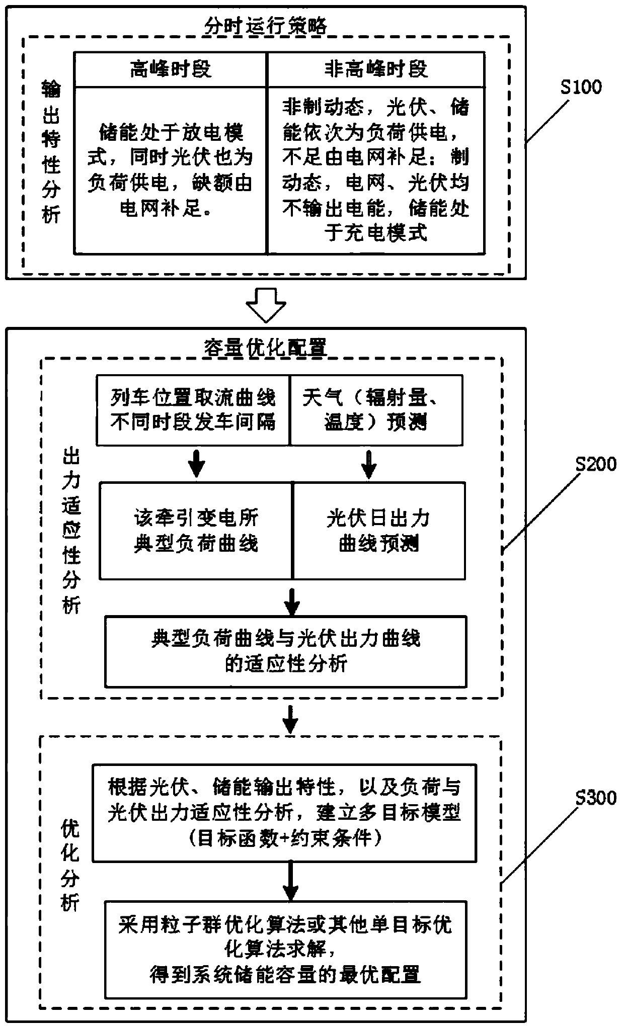
[0059] In this embodiment, see figure 1 As shown, the present invention proposes a capacity optimization configuration method for urban rail transit photovoltaic energy storage system,

[0060] A capacity optimization configuration method for urban rail transit photovoltaic energy storage system includes the steps:

[0061] S100: Develop a time-sharing operation strategy based on the operation status of urban rail transit with large peak loads in the morning and evening to determine the operation status of photovoltaic, energy storage and power grids at different times;

[0062] S200, according to the output adaptability of the typical daily load curve and photovoltaic output curve, comprehensively analyze the time-sharing operation characteristics and output adaptability of photovo...


PUM


Abstract

The invention discloses a capacity optimization configuration method for an urban rail transit photovoltaic energy storage system. The method comprises the steps: formulating a time-sharing operationstrategy according to the operation characteristics that the morning and evening peak load capacities of urban rail transit are large to determine operation states of photovoltaic, energy storage andpower grid at different time periods; researching a typical daily load curve and a photovoltaic output curve to carry out output adaptability analysis, and establishing an optimization model taking voltage fluctuation and economy as target functions by integrating photovoltaic and energy storage time-sharing operation characteristics and output adaptability analysis; converting multiple targets into a single-target optimization function in a weight assignment mode; carrying out solving through a particle swarm optimization algorithm to obtain optimal configuration of the energy storage capacity of the system. The method facilitates energy conservation and emission reduction of the urban rail system and local photovoltaic absorption, meanwhile, reduces network voltage fluctuation to improvethe traction side electric energy quality; and time-sharing operation is achieved, photovoltaic peak clipping and valley filling and load peak clipping are conducted through energy storage, and the economical efficiency of the system can be improved.

Description

Technical field [0001] The invention belongs to the technical field of urban rail transit power supply systems, and particularly relates to a capacity optimization configuration method of an urban rail transit photovoltaic energy storage system. Background technique [0002] With the improvement of the national economy and the acceleration of urbanization, urban rail transit has developed rapidly in large and medium-sized cities in China, ushering in a new era of comprehensive development. Under the traditional energy structure model, large-scale electricity consumption will bring about huge energy consumption and make environmental pollution more serious, which will greatly affect the urban environment and sustainable development. Therefore, the access to renewable energy such as solar energy and wind energy is of great significance to the green development of urban rail transit and energy conservation and emission reduction. [0003] At present, as the most ideal and cleanest en...

Claims


Application Information

Patent Timeline
Patent Type & Authority Applications(China)
IPC IPC(8): H02J1/10H02J1/14
CPCH02J1/10H02J1/14
Inventor 宋昕党敏王振海陈霞张晔韩正平徐海彬戴朝华韩春白雪张丽
Owner 北方国际合作股份有限公司
Learn More