
Physical vapor deposition equipment used for thick film deposition

A physical vapor deposition and equipment technology, used in ion implantation plating, metal material coating process, coating and other directions, can solve the problems of poor cooling and temperature control of wafers, deposition chambers and process suites, and achieve good heat dissipation. , the effect of improving the degree of freedom of adjustment

Active Publication Date: 2020-01-10
BETONE TECH SHANGHAI
View PDF7 Cites 17 Cited by
  • Summary
  • Abstract
  • Description
  • Claims
  • Application Information

AI Technical Summary

Problems solved by technology

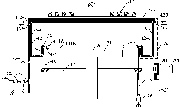
[0006] In view of the above-mentioned shortcoming of prior art, the object of the present invention is to provide a kind of physical vapor deposition equipment for thick film deposition, for solving the physical vapor deposition for thick film deposition of adopting sputtering process in the prior art During the deposition process, the equipment has poor cooling and temperature control effects on wafers, deposition chambers and process kits, etc.

Method used


Image

  • Physical vapor deposition equipment used for thick film deposition
  • Physical vapor deposition equipment used for thick film deposition
  • Physical vapor deposition equipment used for thick film deposition

Examples


Embodiment Construction

[0045] Embodiments of the present invention are described below through specific examples, and those skilled in the art can easily understand other advantages and effects of the present invention from the content disclosed in this specification. The present invention can also be implemented or applied through other different specific implementation modes, and various modifications or changes can be made to the details in this specification based on different viewpoints and applications without departing from the spirit of the present invention.

[0046] For example, when describing the embodiments of the present invention in detail, for the convenience of explanation, the cross-sectional view showing the device structure will not be partially enlarged according to the general scale, and the schematic diagram is only an example, which should not limit the protection scope of the present invention. In addition, the three-dimensional space dimensions of length, width and depth sho...


PUM

PropertyMeasurementUnit
thicknessaaaaaaaaaa
diameteraaaaaaaaaa

Abstract

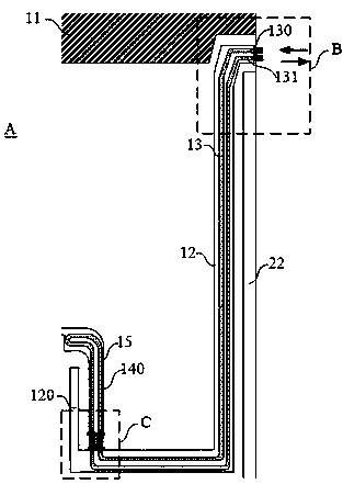
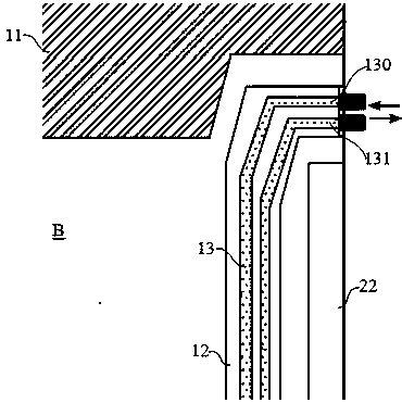
The invention provides physical vapor deposition equipment used for thick film deposition. The physical vapor deposition equipment comprises a permanent magnet device, a target material, a wafer baseand a cavity wall, and further comprises a cavity wall baffle, a wafer shield ring and a shield ring supporting and adjusting device. One end of the cavity wall baffle is fixed between the target material and the cavity wall, the other end of the cavity wall baffle is a free end, and a first cooling pipe cavity used for containing a cooling pipe is arranged in the cavity wall baffle. The wafer shield ring comprises a vertical portion and a horizontal portion, the horizontal portion is annularly arranged on the upper edge of the wafer, the vertical portion is arranged on the periphery of the lower portion of the horizontal portion, a second cooling pipe cavity used for containing a cooling pipe is arranged in the vertical portion, and a groove is formed in the end, close to the vertical portion, of the horizontal portion. The shield ring supporting and adjusting device comprises an ejector pin, an ejector pin ring, a connecting rod and a transmission mechanism. One end of the ejector pin is inserted into the groove, the other end of the ejector pin is fixedly connected with the ejector pin ring, the ejector pin ring is connected with the transmission mechanism arranged on the outerportion through the connecting rod, and the ejector pin ring surrounds the periphery of the wafer base. According to the equipment, cooling and temperature control to the wafer, a deposition cavity and a process set can be effectively achieved in the deposition process.

Description

technical field [0001] The invention relates to the technical field of semiconductor manufacturing equipment, in particular to a physical vapor deposition equipment for thick film deposition. Background technique [0002] In the semiconductor manufacturing process, it is often necessary to use physical vapor deposition equipment to deposit thin films on the surface of wafers or devices. The main physical vapor deposition techniques are evaporation and sputtering. The saturated vapor pressure of the object at high temperature is used for coating deposition; the latter uses the ions generated by the plasma to bombard the electrode of the object to be sputtered by the ions, so that the gas phase of the plasma contains the particles of the object to be plated, Deposition is then performed. [0003] In the field of integrated circuit, power device and discrete device manufacturing, with the development of technology, in order to obtain high current density, high-power devices us...

Claims


Application Information

Patent Timeline
Patent Type & Authority Applications(China)
IPC IPC(8): C23C14/35C23C14/04C23C14/54
CPCC23C14/042C23C14/35C23C14/541
Inventor 宋维聪周云睢智峰
Owner BETONE TECH SHANGHAI
Learn More