Horizontal flow precipitation water collecting device

A water collection device and advection sedimentation technology, which is applied in the direction of sedimentation separation, feeding/discharging device of sedimentation tank, sedimentation tank, etc., can solve the problems of reduced sedimentation area, high load on the weir, troublesome cleaning, etc., and achieve the improvement Effects of water production capacity, reduction of catchment area, and increase in load rate

A water collection device and advection sedimentation technology, which is applied in the direction of sedimentation separation, feeding/discharging device of sedimentation tank, sedimentation tank, etc., can solve the problems of reduced sedimentation area, high load on the weir, troublesome cleaning, etc., and achieve the improvement Effects of water production capacity, reduction of catchment area, and increase in load rate

CN110681189APending Publication Date: 2020-01-14天津市华博水务有限公司

Image

  • Horizontal flow precipitation water collecting device
  • Horizontal flow precipitation water collecting device
  • Horizontal flow precipitation water collecting device

Examples


Embodiment 1

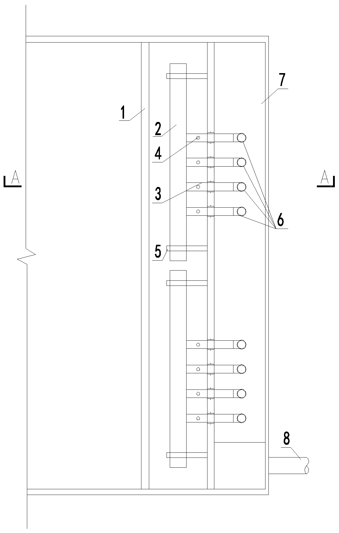
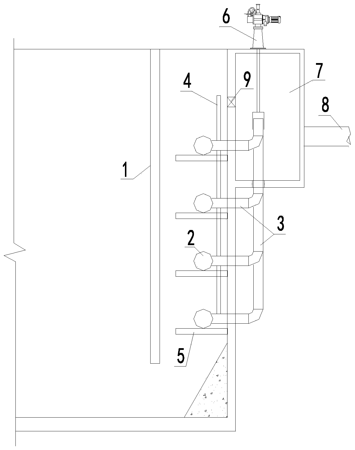
[0022] Such as figure 1 , figure 2 and Figure 5 As shown, the present invention provides an advection sedimentation water collection device, comprising a device body and an outlet channel 7, the outlet channel 7 is used to collect water, the device body is a cuboid structure, and the outlet channel 7 is arranged on the On the outer wall of the device body, a rectification wall 1 and a water collection assembly are arranged in the device body, and the rectification wall 1 can better rectify the hydraulic flow state, wherein the water collection assembly includes a perforated water collection pipe 2, a water outlet pipe 3 and the water outlet control gate 6, the perforated water collection pipe 2 is arranged in layers, and considering the hydraulic balance, the service area of ​​a single pipe does not exceed 5m×0.5m, and the perforated water collection pipe 2 is connected to one end of the water outlet pipe 3, so The other end of the outlet pipe 3 extends into the outlet cha...

Embodiment 2

[0024] This embodiment is basically the same as the first embodiment, and only the differences will be described below.

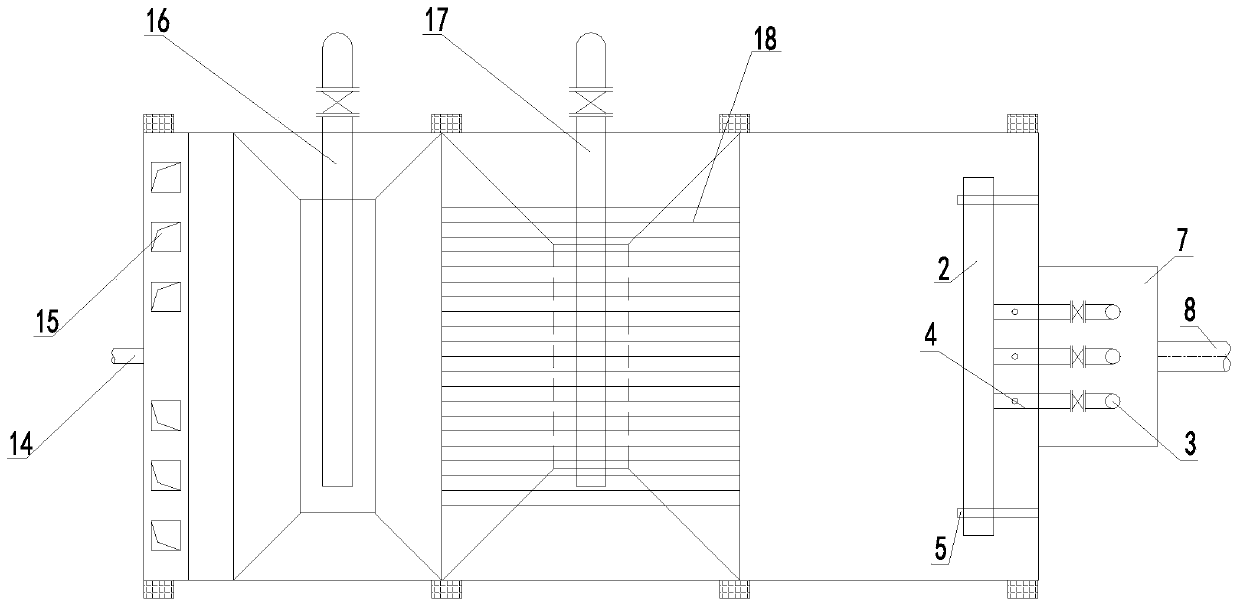
[0025] Such as image 3 and Figure 4 As shown, in this embodiment, the device body is different from that in Embodiment 1. The device body in this embodiment includes a water distribution area 10, a transition area 11, a sedimentation area 12 and a water collection area 13. The water replenishment area A water inlet 14 is provided on the side wall of 10, and a water distribution tank 15 is provided at the position of the water inlet 14 in the water distribution area 10, and a hole groove is opened at the lower end of the water distribution tank 15, and the water supply area 10 and the transition area 12 A screen grid is set, and the transition zone 11 is used to preliminarily settle the sediment in the water body. The lower end of the transition zone 11 is an inverted truncated pyramid structure, and the first sewage pipe 16 is set in the structure, so A...


PUM


Abstract

The invention relates to a horizontal flow precipitation water collecting device, which comprises a device body and a water outlet ditch, wherein the device body is a cuboid structure, the water outlet ditch is arranged on the outer wall of the device body, a rectifying wall and a water collecting assembly are arranged in the device body, the water collecting assembly comprises a perforated watercollecting pipe, a water outlet pipe and a water outlet control gate, the perforated water collecting pipe is connected to one end of the water outlet pipe, the other end of the water outlet pipe extends into the water outlet ditch, the water outlet control gate is connected to the end, extending into the water outlet ditch, of the water outlet pipe through a pipeline, and a gap is formed in the connecting position of the pipeline and the water outlet pipe. Compared with the form of the water collecting groove, the device of the invention substantially reduces the water collecting area, so that the proportion of the effective precipitation area of the precipitation pond is large, and the load rate of the existing horizontal flow precipitation is obviously improved so as to improve the water production capacity of the system.

Description

technical field [0001] The invention relates to the technical field of advection mud-water sedimentation and separation in sewage treatment and water supply treatment, in particular to an advection sedimentation water collection device. Background technique [0002] In the treatment of sewage and water supply in the form of advection sedimentation, water collection tanks (triangular weirs, perforated tanks, etc.) are generally used to collect the clear water after mud-water separation. The water collection tanks are arranged on the water surface. In this form, sunlight will Algae breed in the sump, which is very troublesome to clean up, resulting in increased manual labor, and there are safety hazards in cleaning; the water collection section in the form of the original sump will cause a large change in the hydraulic flow state, not only the change in the hydraulic flow state of the water collection area, Its change will also extend to the front sedimentation section, result...

Claims


Application Information

Patent Timeline
14 Jan 2020
Publication
CN110681189A
IPC
B01D21/02; B01D21/24
CPC
B01D21/02; B01D21/245; B01D21/0033
Inventors
陈凡阵; 郭金玲