Direct current centralized control system

A technology of centralized control system and energy storage system, applied in general control system, control/regulation system, program control and other directions, can solve problems such as hidden safety hazards and long cable consumption, prevent circulation, shorten cable length, and ensure system safe effect

Pending Publication Date: 2020-01-14
HENAN RUITONG ELECTRIC TECH CO LTD
View PDF0 Cites 4 Cited by
  • Summary
  • Abstract
  • Description
  • Claims
  • Application Information

AI Technical Summary

Problems solved by technology

[0005] The purpose of the present invention is to provide a DC centralized control system, which solves the problem that the connection mode in the battery room of the existing energy storage container consumes a long cable length and there are potential safety hazards in the direct connection of the BMS to the PCS

Method used


Image

  • Direct current centralized control system
  • Direct current centralized control system

Examples


Embodiment 1

[0034] Explanation of technical terms:

[0035] BMS: Battery Management System, battery management system, can improve the utilization rate of the battery and prevent the battery from overcharging and over-discharging.

[0036] PCS: Power Conversion System, energy storage converter, can control the charging and discharging process of the battery, perform AC-DC conversion, and can directly supply power to AC loads without a grid. Communicate with the BMS through the CAN interface to obtain the status information of the battery pack, which can realize the protective charging and discharging of the battery and ensure the safe operation of the battery.

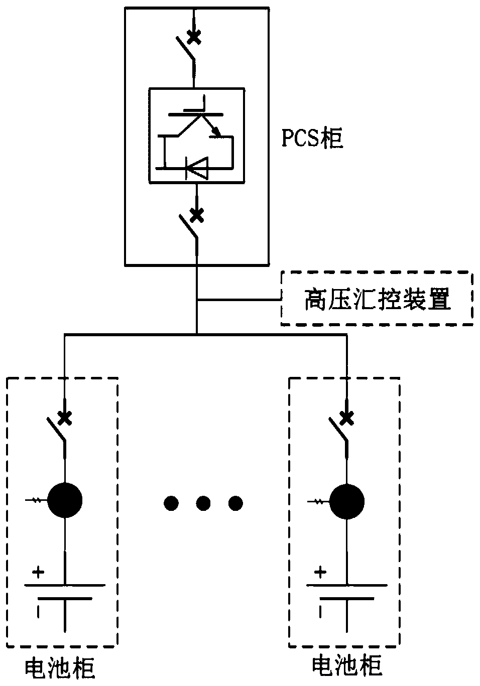
[0037] A preferred embodiment of the present invention provides a DC centralized control system, which is arranged in an energy storage container and includes two sets of energy storage systems. The energy storage system includes several battery cabinets connected in parallel, connected to several battery cabinets The PCS cabinet...


PUM


Abstract

The invention discloses a direct current centralized control system and belongs to the energy storage container technology field. The system is arranged in an energy storage container, and comprises two groups of energy storage systems. Each energy storage system comprises a plurality of battery cabinets connected in parallel, a PCS cabinet connected with the plurality of battery cabinets, and a high-voltage control device connected with direct current sides of the plurality of battery cabinets in parallel. The high-voltage control device comprises an energy storage centralized controller anda BMS communicated and connected with the energy storage centralized controller, and the energy storage centralized controller and the BMS are connected with the PCS cabinet. In the invention, problems that a length of a consumed cable is relatively long in a connection mode in a battery room in an existing energy storage container and potential safety hazards exist when the BMS is directly connected to the PCS are solved.

Description

technical field [0001] The invention belongs to the technical field of energy storage containers and relates to a direct current centralized control system. Background technique [0002] Since the energy required by people has strong time and space, in order to use energy reasonably and improve energy utilization, it is necessary to use a device to collect and store the excess energy that is not used for a period of time in a certain way. Get up, and then extract and use it when it is used at a peak, or transport it to a place where energy is scarce, and this method is energy storage. Energy storage mainly includes the storage of thermal energy, kinetic energy, electric energy, electromagnetic energy, chemical energy and other energy. At present, the research, development and application of energy storage technology is mainly based on the storage of thermal energy and electric energy, which are widely used in solar energy utilization and "mobile" of electric power. peak fil...

Claims


Application Information

Patent Timeline
Patent Type & Authority Applications(China)
IPC IPC(8): G05B19/05H02J13/00
CPCG05B19/054G05B2219/1103
Inventor 李军伟任封娟武松辉张培涛柴修江
Owner HENAN RUITONG ELECTRIC TECH CO LTD
Why Eureka
Try Eureka