
Rock core pipe cutting machine

A cutter and core tube technology, which is used in grinding machines, grinding machine parts, grinding/polishing equipment, etc., can solve problems such as inability to apply, mutual contamination of samples, secondary pollution, etc., and achieve easy comparison of horizons , avoid secondary pollution, improve work efficiency

Pending Publication Date: 2020-01-17
YUNNAN NORMAL UNIV +1
View PDF0 Cites 3 Cited by
  • Summary
  • Abstract
  • Description
  • Claims
  • Application Information

AI Technical Summary

Problems solved by technology

But all there is very big limitation in these methods and equipment, mainly shows in: (1) rock core cutting machine equipment is very heavy, and needs 220V alternating current, can not be applied to the field work of field drilling (as Holland Avaatech produces rock core cutting machine dead weight 340kg, and the movement of the cutting component is driven by the rotation of the screw, the noise is extremely high), and the equipment can only cut core tubes with one diameter; (2) It is difficult to avoid the disturbance of the saw blade to some samples during the process of manually cutting the sample tube , resulting in mutual contamination of samples from different layers, which is very time-consuming and labor-intensive, and the operator’s hands are easily injured; (3) The core is ejected with a rubber plug, and the core has the disadvantages of volume compression and secondary pollution during the process of exiting the tube, which destroys the The original structure of the sediment, the depth of the sediment and the error of the deposition rate are greatly increased, which greatly reduces the credibility of the research results

Method used


Image

  • Rock core pipe cutting machine
  • Rock core pipe cutting machine
  • Rock core pipe cutting machine

Examples


Embodiment Construction

[0035] Various exemplary embodiments of the present invention will now be described in detail with reference to the accompanying drawings. It should be noted that the relative arrangements of components and steps, numerical expressions and numerical values ​​set forth in these embodiments do not limit the scope of the present invention unless specifically stated otherwise.

[0036] The following description of at least one exemplary embodiment is merely illustrative in nature and in no way taken as limiting the invention, its application or uses.

[0037] Techniques and devices known to those of ordinary skill in the relevant art may not be discussed in detail, but where appropriate, such techniques and devices should be considered part of the description.

[0038] In all examples shown and discussed herein, any specific values ​​should be construed as exemplary only, and not as limitations. Therefore, other instances of the exemplary embodiment may have different values.

...


PUM


Abstract

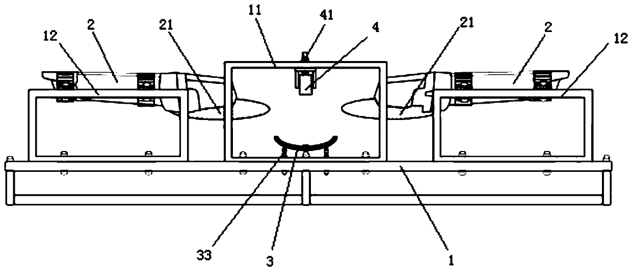
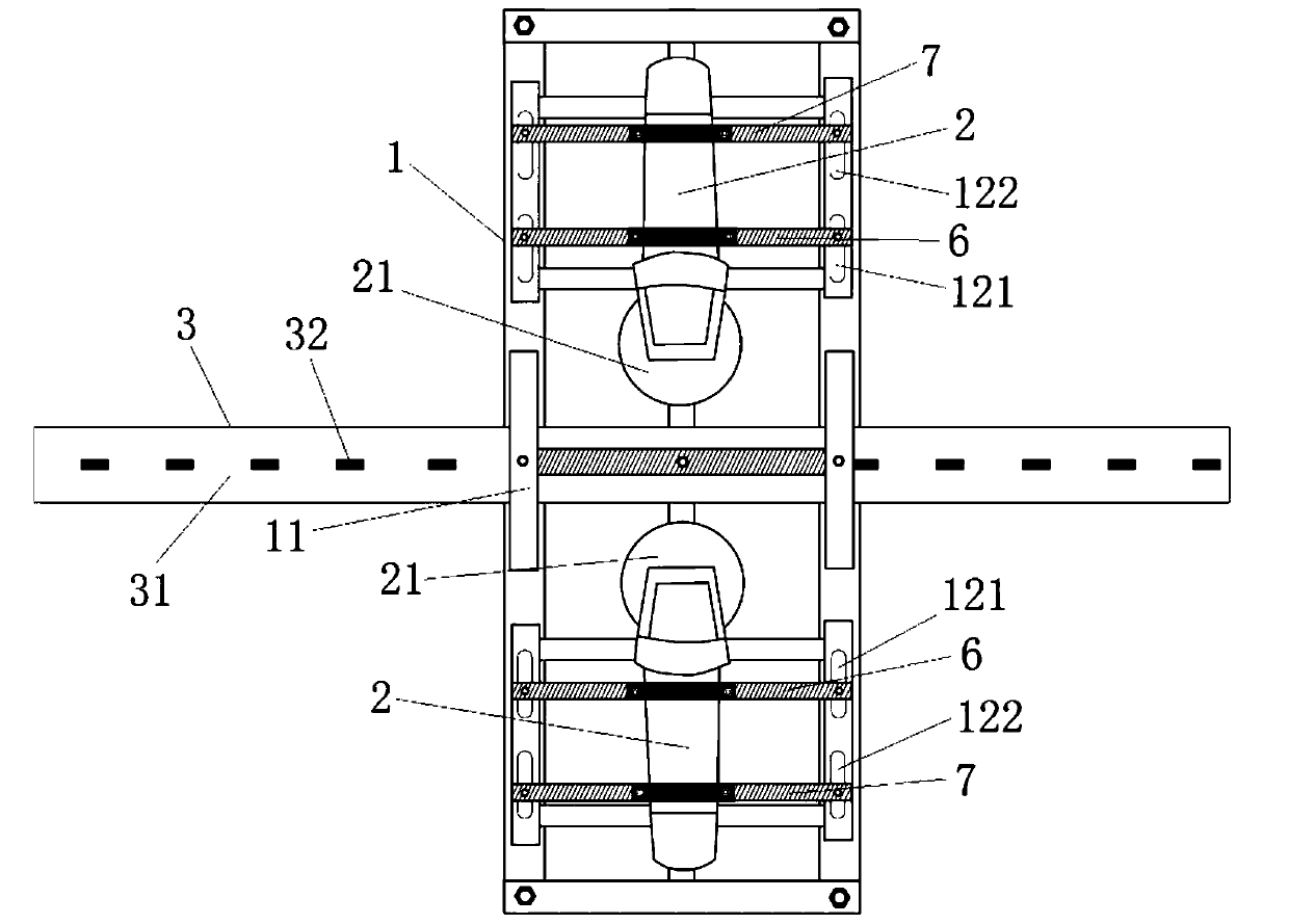
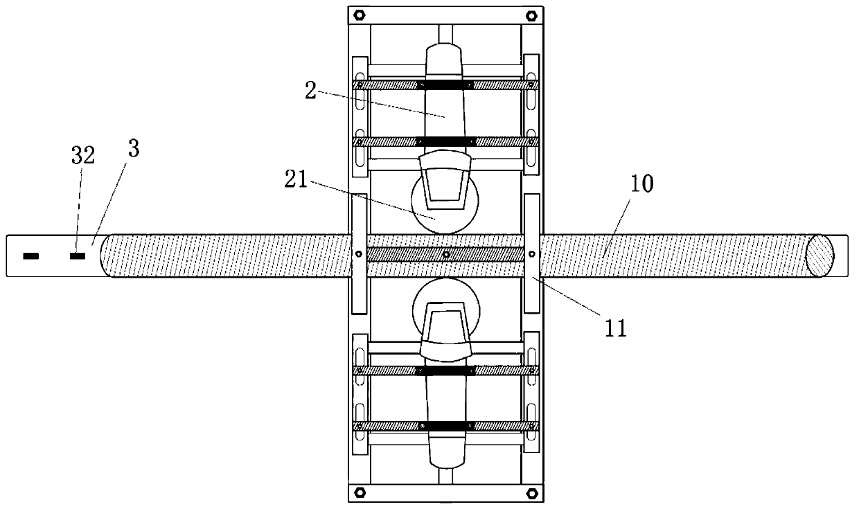
The invention discloses a rock core pipe cutting machine. The cutting machine comprises a frame body, and two angle grinding machines oppositely arranged on the frame body and configured to leave a spacing distance between cutting blades thereof for placing rock core pipes, wherein the cutting blades of the angle grinding machines correspond to the outer side walls of the rock core pipes; the axial direction of the rock core pipes is a first direction; a direction perpendicular to the first direction in the horizontal plane is a second direction; a direction perpendicular to the first direction and the second direction is a third direction; and rotating shafts of the cutting blades of the angle grinding machines are arranged in the third direction. The cutting machine further comprises a slide way for bearing the rock core pipes; and the slide way extends in the first direction. The rock core pipes can be conveniently, quickly and accurately cut off in the axial direction thereof in the drilling scene; and rock cores are not disturbed in the cutting process, so that the secondary pollution of rock core samples can be totally prevented, the working efficiency is greatly improved, and the reliable guarantee is provided for obtaining of continuous complete sediment rock core samples to meet the research demands.

Description

technical field [0001] The invention relates to a cutting instrument. More particularly, it relates to a core barrel cutter. Background technique [0002] In the context of global warming, it is imminent to explore the factors affecting global change and the regularity of global climate change. Stratigraphic (lake) sediments contain rich environmental change information in the past, which can be used to reconstruct paleoclimate and paleoenvironment based on these information, and then summarize the laws of climate change, providing an indispensable background for predicting possible future climate and environmental changes Conditional and analogy patterns. Therefore, stratigraphic (lake) sediments are one of the main carriers in the field of global change research. [0003] At present, the extraction of sediments mainly relies on equipment such as gravity drills, piston drills, and vibratory drills. Plastic pipes such as PVC are used as core pipes to remove sediments from...

Claims


Application Information

Patent Timeline
Patent Type & Authority Applications(China)
IPC IPC(8): B26D1/24B26D7/02B26D3/00B26D7/06B26D7/27B24B27/06B24B41/00B24B41/06
CPCB24B27/06B24B27/0683B24B41/005B24B41/06B26D1/24B26D3/001B26D7/02B26D7/0641B26D7/27B26D2007/013
Inventor 蒙红卫沈才明马玉贞孙启发王朋王敏
Owner YUNNAN NORMAL UNIV
Learn More