
Gravity type heat transfer device and preparation method thereof

A heat transfer, gravity-type technology, applied in the field of heat transfer, can solve the problems of reduced contact angle between the liquid working medium and the inner surface of the device, low frequency of gas-liquid phase change cycle, difficulty in the return of liquid working medium, etc., to achieve production The effect of low technical difficulty, light weight and high heat transfer density

Active Publication Date: 2020-01-17
GUANGZHOU SHIYUAN ELECTRONICS CO LTD
View PDF4 Cites 0 Cited by
  • Summary
  • Abstract
  • Description
  • Claims
  • Application Information

AI Technical Summary

Problems solved by technology

In order to meet the trend of miniaturization and thinning of electronic products, the volume of heat transfer devices is also continuously reduced. However, when working with small-diameter heat transfer tubes or ultra-thin heat transfer plates, they all face slow flow rate of working fluid, gas-liquid phase The problem of low variable cycle frequency
The reason is that the surface tension effect of the liquid working medium is greater than the effect of gravity, making it difficult to reflow. For example, for some metal devices, due to the requirements of the metal material manufacturing process, the metal surface is covered with oil. Such heat transfer devices will make the liquid The contact angle between the working fluid and the inner surface of the device decreases, making it difficult for the liquid working fluid to flow back

Method used


Image

  • Gravity type heat transfer device and preparation method thereof
  • Gravity type heat transfer device and preparation method thereof
  • Gravity type heat transfer device and preparation method thereof

Examples


Embodiment 1

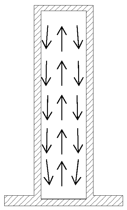
[0038] The gravity heat transfer device of the present embodiment, as Figure 4 Shown is a cross-sectional view of a gravity heat pipe as an example. The gravity heat transfer device includes a heat transfer body 1 and a liquid working medium 2. The heat transfer body 1 encloses a first cavity 13, and the first cavity 13 is A closed space, the liquid working medium 2 is located in the first cavity 13 , the heat transfer body 1 includes the heat transfer shell 11 and the separation layer 12 , the separation layer 12 covers the inner wall of the heat transfer shell 11 . Through the setting of the separation layer 12, the surface energy between the liquid working medium and the surface in contact with it is reduced, the contact angle is increased, and the effect of increasing the phase change cycle speed of the working medium and enhancing the heat transfer efficiency of the heat exchanger is achieved.

[0039] As a specific embodiment, the separation layer 12 is obtained by perf...

Embodiment 2

[0041] This embodiment provides a kind of preparation method of the gravity heat transfer device of embodiment 1, comprises the following steps:

[0042] S1: Manufacture the heat transfer shell, and the two ends of the heat transfer shell are open;

[0043] S2: Surface treatment is performed on the inner surface of the heat transfer shell by a plating process, and an isolation layer is formed that is isolated from the liquid working medium;

[0044] S3: The surface-treated heat transfer shell is edge-sealed by welding, and a liquid injection hole is reserved at any position of the heat transfer shell;

[0045] S4: inject the liquid working medium—HFC refrigerant into the first cavity through the liquid injection hole;

[0046] S5: pumping out the air in the first cavity to form a vacuum;

[0047] S6: closing the liquid injection hole.

[0048] The preparation method of the gravity heat transfer device in this embodiment has simple process steps and low production technical ...

Embodiment 3

[0050] This embodiment provides another preparation method of the gravity heat transfer device of embodiment 1, comprising the following steps:

[0051] S1: An aluminum hollow profile with a cavity structure is prepared by extrusion molding as a heat transfer shell, and the volume of the cavity is controlled by the design of the molding die;

[0052] S2: Surface treatment is carried out to the hollow aluminum profile through a dip coating process, and a separation layer is formed which is separated from the liquid working medium, so that the contact angle between the liquid working medium of the heat transfer device—ethanol and the surface of the separation layer is greater than 90° (such as Figure 5 As shown, the contact angle is the θ angle in the figure), the specific operation method is: when the contact angle is greater than 90°, proceed to the next step; when the contact angle is not greater than 90°, continue the surface treatment or adjust the surface treatment process...


PUM


Abstract

The invention relates to a gravity type heat transfer device and a preparation method thereof. The gravity type heat transfer device comprises a heat transfer device body and a liquid working medium,wherein the heat transfer device body comprises a heat transfer device shell and an alienation layer, and the alienation layer covers the inner wall of the heat transfer device shell. The preparationmethod comprises the following steps of manufacturing a heat transfer device shell, and opening two ends of the heat transfer device shell; performing surface treatment on the inner surface of the heat transfer device shell to reduce surface energy; sealing the edges of surface treated heat transfer device shell through welding, and reserving a liquid injection hole at any position of the heat transfer device shell; injecting the liquid working medium through the liquid injection hole into a heat transfer device inner cavity; extracting the air in the heat transfer device inner cavity to forma vacuum; and sealing the liquid injection hole. The gravity type heat transfer device is high in heat transfer density, good in temperature uniformity, simple in structure, light in weight, high in reflux efficiency after liquid working medium condensation, simple in preparation method process and convenient to operate.

Description

technical field [0001] The invention relates to the technical field of heat exchangers, in particular to a gravity heat exchanger and a preparation method thereof. Background technique [0002] With the development of technology in the electronics industry, the performance and power of electronic components have been continuously improved, and the heat flux has increased sharply. At the same time, the volume of electronic devices has continued to shrink, which greatly affects the life and performance of electronic products. To improve product reliability and prolong service life has become a major issue in the industry. [0003] With the development of demand, some advanced heat transfer and cooling technologies have appeared on the market. Phase change heat transfer technology is one of the heat transfer and cooling solutions with strong competitiveness. Its working principle is to use the evaporation and condensation of the liquid working medium, that is, the gas-liquid p...

Claims


Application Information

Patent Timeline
Patent Type & Authority Applications(China)
IPC IPC(8): F28D15/04
CPCF28D15/0283F28D15/04
Inventor 冯先强
Owner GUANGZHOU SHIYUAN ELECTRONICS CO LTD
Learn More