Supercharge Your Innovation With Domain-Expert AI Agents!

Rotary steerable drilling system and its control method

A technology of rotary steerable drilling and directional well, which is applied in the automatic control system of drilling, directional drilling, rotary drilling and other directions, can solve the problems of inconvenient use and maintenance, reduce installation and use costs, and reduce directional support pressure. , the effect of increasing drilling speed

Active Publication Date: 2021-04-16
陕西乾悦通能源工程有限公司
View PDF5 Cites 0 Cited by
  • Summary
  • Abstract
  • Description
  • Claims
  • Application Information

AI Technical Summary

Problems solved by technology

[0004] Therefore, the embodiment of the present invention provides a rotary steerable drilling system and its control method to solve the problem of inconvenient use and maintenance in the prior art due to the closed-loop control system being installed underground

Method used


Image

  • Rotary steerable drilling system and its control method
  • Rotary steerable drilling system and its control method
  • Rotary steerable drilling system and its control method

Examples


Embodiment 1

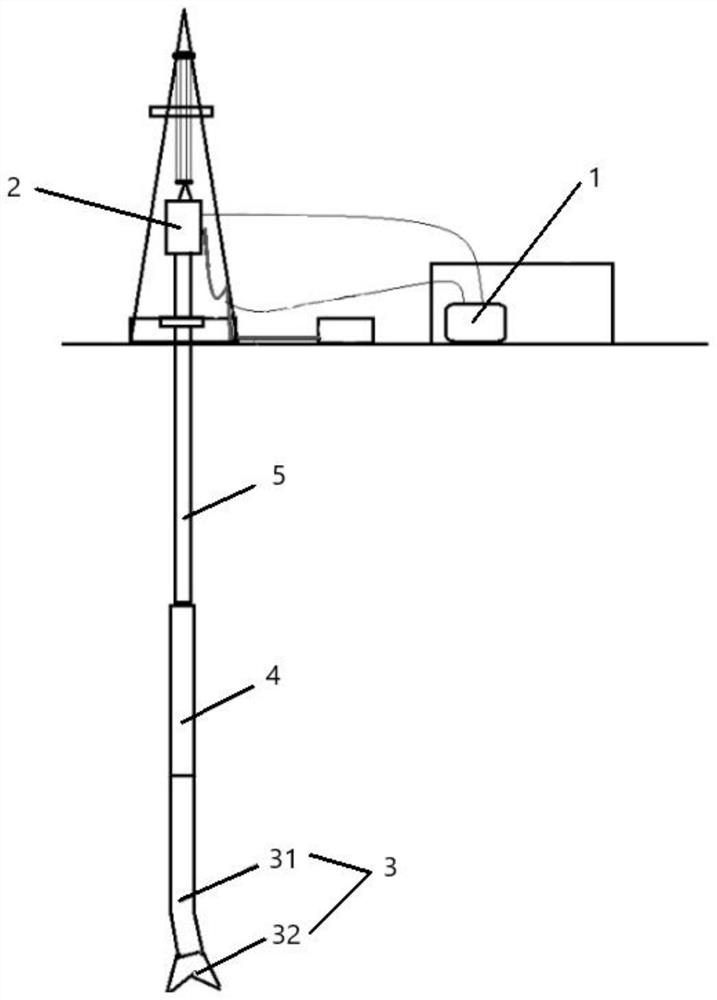
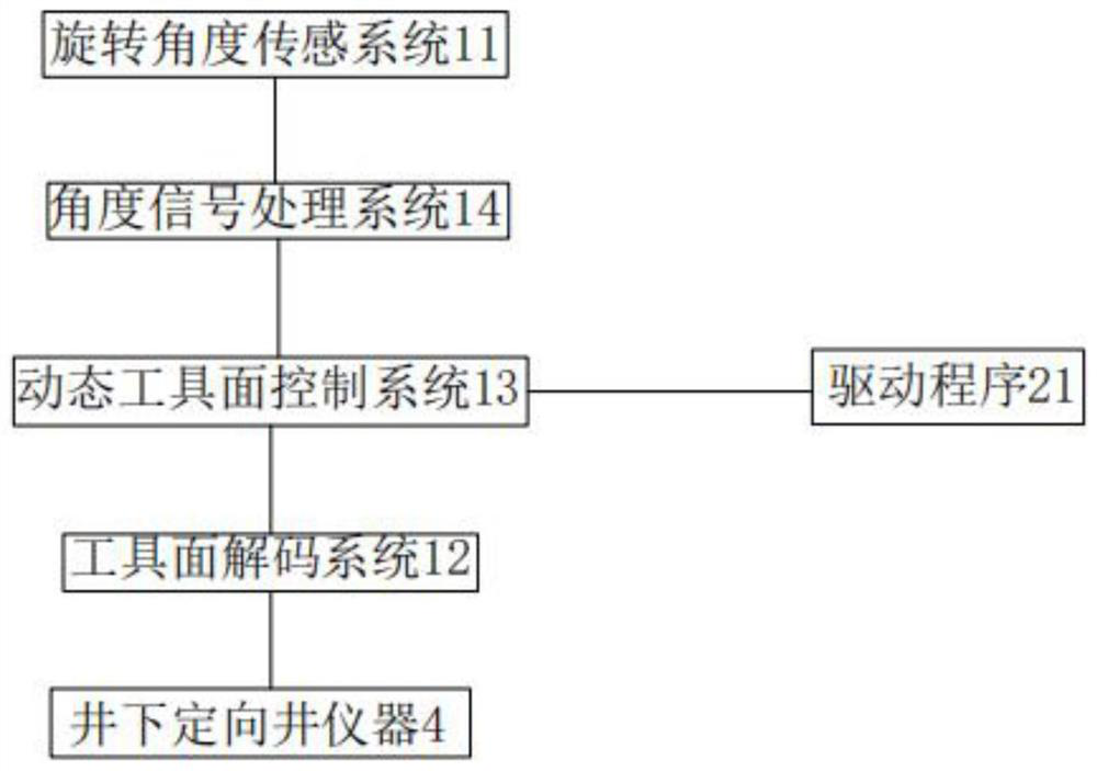
[0038] A rotary steerable drilling system incorporating figure 1 and figure 2 , including an industrial computer 1 , a rotating device 2 , a bottom directional drilling tool 3 , a downhole directional well tool 4 and a drill string 5 .

[0039] The rotating device 2 includes a driver 21, a motor and a rotating machine; the driver 21 receives instructions from the industrial computer 1 to control the motor, the rotating machine is connected to the drill string 5, and the motor drives the rotating machine to drive the drill string 5 to rotate, and the motor is Any one of DC motor, AC motor, variable frequency motor, stepping motor or servo motor, the rotating machine is a turntable or top drive, and the specific structure of the rotating device 2 is the prior art, and will not be described here.

[0040] The upper end of the drill string 5 is connected to the rotary device 2, and the lower end is connected to the bottom directional drilling tool 3. The drill string 5 is the hu...

Embodiment 2

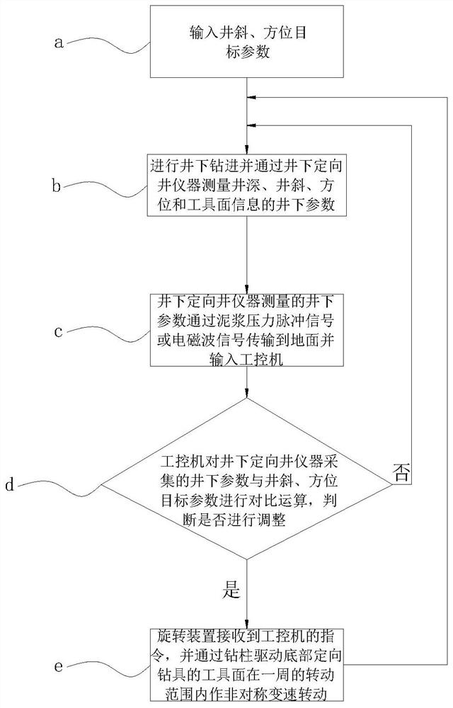
[0051] A control method of the rotary steerable drilling system in Embodiment 1, such as image 3 shown, including the following steps:

[0052] Step a, input well deviation and azimuth target parameters in industrial computer 1;

[0053] Step b, carry out downhole drilling and measure downhole parameters such as well depth, well deviation, azimuth and tool face information through downhole directional well instrument 4;

[0054] Step c, the downhole parameters measured by the downhole directional well tool 4 are transmitted to the ground through the mud pressure pulse signal or electromagnetic wave signal and input into the industrial computer 1;

[0055] Step d, the industrial computer 1 compares the downhole parameters collected by the downhole directional well instrument 4 with the well deviation and azimuth target parameter data, and the specific calculation method of the industrial computer 1 is:

[0056] The high side of the wellbore is the initial phase θ1, so that t...


PUM


Abstract

The embodiment of the invention discloses a rotary steerable drilling system and its control method, belonging to the technical field of petroleum and rock and mine drilling engineering, wherein the main points of the technical solution of the rotary steerable drilling system include industrial computer, rotary device, bottom directional drilling tool, downhole Directional well tool and drill string; the downhole directional well tool is set on the bottom directional drilling tool for measurement while drilling; the upper end of the drill string is connected to the rotating device, and the lower end of the drill string is connected to the bottom directional drilling tool; the data collected by the downhole directional well tool is passed through The drilling fluid is transported to the ground and input into the industrial computer; the industrial computer is set on the ground to control the rotating device. It can reduce installation and use costs, facilitate maintenance, and at the same time reduce supporting pressure and improve drilling efficiency.

Description

technical field [0001] Embodiments of the present invention relate to the technical field of petroleum and rock and mine drilling engineering, and in particular to a rotary steerable drilling system and a control method thereof. Background technique [0002] Rotary steerable drilling system is a cutting-edge automatic drilling technology. In terms of technology, there are three mainstream design methods: static pointing, dynamic pointing, and static pushing. This technology has become an essential technology for complex ultra-deep directional wells and extended-reach horizontal wells. [0003] The closed-loop control system of the existing rotary steerable well system is set downhole, and the downhole instruments of the control system will be limited by conditions such as borehole size, ambient temperature, instrument power supply, signal transmission, and control means. It is also necessary to lift all the downhole equipment to the ground for maintenance, the maintenance ...

Claims


Application Information

Patent Timeline
Patent Type & Authority Patents(China)
IPC IPC(8): E21B7/04E21B44/00E21B47/12E21B3/02E21B47/022E21B47/04
CPCE21B3/02E21B7/04E21B44/00E21B47/022E21B47/04E21B47/12
Inventor 王克行
Owner 陕西乾悦通能源工程有限公司
Features
  • R&D
  • Intellectual Property
  • Life Sciences
  • Materials
  • Tech Scout
  • Unparalleled Data Quality
  • Higher Quality Content
  • 60% Fewer Hallucinations
Learn More