
Method for improving laser emission source, laser emission source and photo-etching system

A laser emission and emission source technology, applied in the laser field, can solve the problems of reduced production capacity, long reaction time, and increased time spent in the preparation process of semiconductor devices, and achieve the effect of shortening operation time and increasing production capacity

Inactive Publication Date: 2020-01-24
SHANGHAI HUALI MICROELECTRONICS CORP
View PDF2 Cites 0 Cited by
  • Summary
  • Abstract
  • Description
  • Claims
  • Application Information

AI Technical Summary

Problems solved by technology

[0004] The object of the present invention is to provide a method for improving the laser emission source, the laser emission source and the photolithography system, in order to solve the problem that the existing laser emission source needs a long reaction time to obtain the laser with a specific frequency, and thus causes The time spent in the preparation process of subsequent semiconductor devices increases and the problem of reducing production capacity

Method used


Image

  • Method for improving laser emission source, laser emission source and photo-etching system

Examples


Embodiment Construction

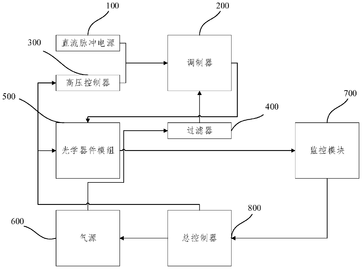
[0023] The following is attached figure 1 and Specific Embodiments A method for improving a laser emission source, a laser emission source, and a photolithography system proposed by the present invention are further described in detail. The advantages and features of the present invention will become clearer from the following description. It should be noted that the drawings are in a very simplified form and all use imprecise scales, which are only used to facilitate and clearly assist the purpose of illustrating the embodiments of the present invention. In order to make the objects, features and advantages of the present invention more comprehensible, please refer to the accompanying drawings. It should be noted that the structures, proportions, sizes, etc. shown in the drawings attached to this specification are only used to match the content disclosed in the specification, for those who are familiar with this technology to understand and read, and are not used to limit th...


PUM


Abstract

The invention discloses a method for improving a laser emission source, the laser emission source and a photo-etching system. The method for improving a laser emission source comprises the following steps: providing a discharge cavity; introducing gas into the discharge cavity; and applying a laser emission voltage and a pulse voltage to the discharge cavity to enable the gas to discharge and generate laser. The method can shorten the starting time and improve the utilization rate of gas.

Description

technical field [0001] The invention relates to the field of laser technology, in particular to a method for improving a laser emitting source, a laser emitting source and a photolithography system. Background technique [0002] Gas laser has the characteristics of simple structure, low cost, convenient operation, uniform working medium, good beam quality, and stable and continuous operation for a long time. It is widely used in the manufacturing process of semiconductor devices. For example, it is applied to a lithography machine in a lithography system as a light source of the lithography machine. [0003] The control laser emission source (light source) of the traditional lithography machine is a high-voltage modulated RF power supply (high-voltage controller), which is connected to the positive and negative stages of a parallel plate in the modulator, and applied A radio frequency voltage, a specific gas is passed between the two parallel plates of the modulator, and th...

Claims


Application Information

Patent Timeline
Patent Type & Authority Applications(China)
IPC IPC(8): H01S3/036H01S3/03H01S3/032G03F7/20
CPCG03F7/70025H01S3/03H01S3/032H01S3/036
Inventor 申亚军尹鹏腾
Owner SHANGHAI HUALI MICROELECTRONICS CORP
Learn More