Method and system for generating chirped Airy vortex electron plasma wave

A plasma and electronic technology, applied in the field of optics, can solve the problems of low efficiency and high cost, and achieve the effect of improving efficiency and saving cost

Active Publication Date: 2020-01-31
SOUTH CHINA NORMAL UNIVERSITY
View PDF4 Cites 6 Cited by
  • Summary
  • Abstract
  • Description
  • Claims
  • Application Information

AI Technical Summary

Problems solved by technology

[0005] The methods of generating chirped Airy vortex electron pl...

Method used


Image

  • Method and system for generating chirped Airy vortex electron plasma wave
  • Method and system for generating chirped Airy vortex electron plasma wave
  • Method and system for generating chirped Airy vortex electron plasma wave

Examples


Embodiment 1

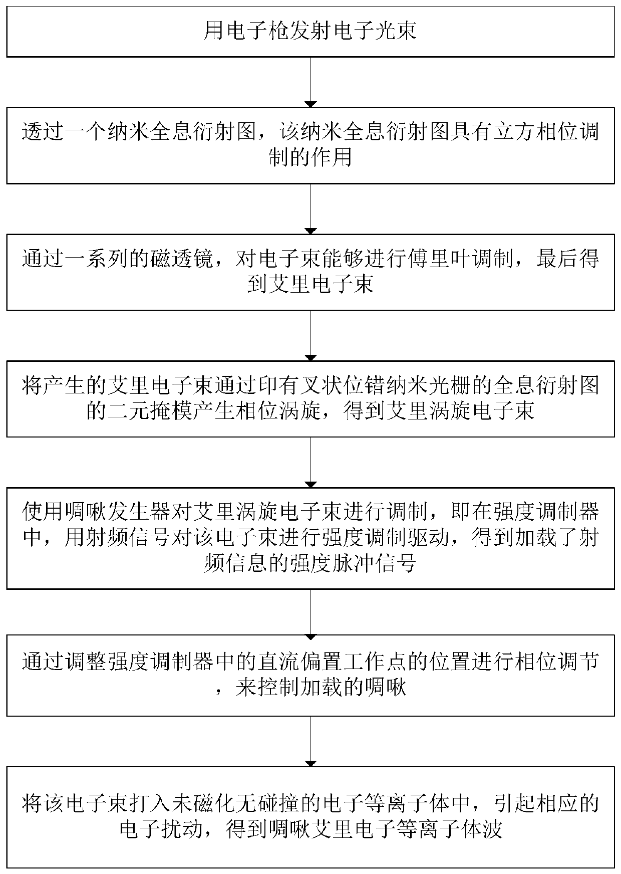
[0040] Such as Figure 1-4 As shown, the present invention provides a method for generating chirped Airy vortex electron plasma waves, comprising:

[0041] First, an electron beam is emitted by an electron gun, and passes through a nano-holographic diffraction pattern, which has the function of cubic phase modulation, that is, adding The hologram is then designed as a binary diffraction grating, following this shape, So in this way the cubic phase is piggybacked on the carrier frequency. Among them, x represents the direction of the x-axis, y represents the direction of the y-axis, and c x is the phase factor in the x-axis direction, c y is the phase factor in the y-axis direction, and Λ is the period of the carrier. S 0 is the ridge height of the binary phase mask. D is an arbitrary duty cycle factor. Then through a series of magnetic lenses, Fourier modulation can be performed on the e-book, and finally the Airy electron beam is obtained. Then, the generated Airy e...

Embodiment 2

[0043] Such as Figure 5 As shown, the present invention also provides a system for generating chirped Airy vortex electron plasma waves, comprising:

[0044] An electron gun for emitting a beam of electrons;

[0045] Nano-holographic diffraction patterns for cubic phase modulation through electron beams;

[0046] The magnetic lens is used to perform Fourier modulation on the electron beam to obtain the Airy electron beam;

[0047]The binary mask is used to pass the generated Airy electron beam through the binary mask printed with the holographic diffraction pattern of the forked dislocation nano-grating to generate a phase vortex to obtain the Airy vortex electron beam;

[0048] The chirp generator is used to modulate the Airy vortex electron beam, that is, in the intensity modulator, the intensity modulation of the electron beam is driven by a radio frequency signal to obtain an intensity pulse signal loaded with radio frequency information;

[0049] an intensity modulato...


PUM


Abstract

The invention discloses a method and system for generating a chirped Airy vortex electron plasma wave. The method comprises the following steps: emitting an electron beam by using an electron gun; performing cubic phase modulation through a nano holographic diffraction pattern; performing Fourier modulation on the electron beam through a magnetic lens to obtain an Airy electron beam; generating aphase vortex by using the generated Airy electron beam through a binary mask of the holographic diffraction pattern printed with a forked dislocation nano grating to obtain an Airy vortex electron beam; modulating the Airy vortex electron beam by using a chirp generator, and performing intensity modulation driving on the electron beam by using a radio frequency signal to obtain an intensity pulsesignal loaded with radio frequency information; performing phase adjustment by adjusting the position of a direct current bias working point in an intensity modulator to control the loaded chirp; anddriving the electron beam into an unmagnetized collision-free electron plasma to cause corresponding electron disturbance to obtain the chirped Airy electron plasma wave. By adoption of the method andsystem disclosed by the invention, the cost is saved, and the generation of the beam can be well controlled.

Description

technical field [0001] The invention relates to the field of optical technology, in particular to a method and system for generating chirped Airy vortex electron plasma waves. Background technique [0002] The interaction between laser and plasma has always been an important part of plasma physics. As early as 1957, Bernstein proposed a series of electromagnetic waves in collisionless plasma. Subsequently, many scientists began to explore electron plasma waves. In 1990, Bantikassen et al. studied a new type of slow electromagnetic wave in paramagnetic plasma. In 2010, Alessandro et al. also studied an Airy plasma wave, which is a non-diffraction surface wave. In 2016, Li Hehe et al. proposed the Airy electron plasma wave. This series of research results has also attracted many scholars to continue in-depth research in the field of electronic plasma waves. [0003] A chirp is a signal whose frequency increases (positive chirp) or decreases (negative chirp) over time. Th...

Claims


Application Information

Patent Timeline
IPC IPC(8): G02B27/00
CPCG02B27/00
Inventor 邓冬梅吴利灿刘煜俊黄诗瑶
Owner SOUTH CHINA NORMAL UNIVERSITY
Why Eureka
Try Eureka