
Kitchen waste stirring kettle reactor

A technology of kitchen waste and stirred tank, which is applied in the field of stirred tank reactors, can solve the problems of complex secondary processing of kitchen waste oil, unsuitable for installation and use in residential areas, long collection and storage time, etc., and achieves a small footprint , reduce emissions and waste of resources, and protect the environment

Pending Publication Date: 2020-02-07
湖北安步环境技术研究有限公司
View PDF0 Cites 4 Cited by
  • Summary
  • Abstract
  • Description
  • Claims
  • Application Information

AI Technical Summary

Problems solved by technology

The scattered collection and storage of food waste takes a long time. The all-in-one machine is equipped with a dehydrator and an oil-water separation device, and a conveying device is needed to transport the dehydrated waste to the reactor. The dehydration, deoiling and conveying devices take up a lot of space. There must be municipal drainage pipes for discharge, and the separated oil must be collected and stored before being transported to a professional treatment plant for treatment. Biodiesel and lubricating oil are produced from kitchen waste oil. The secondary processing process of kitchen waste oil is complex and costly. Existing Technical solution The equipment is complex and takes up a lot of space, and requires municipal sewage pipelines. It is not suitable for placement near residential areas, and is not suitable for installation and use in residential areas.

Method used


Image

  • Kitchen waste stirring kettle reactor
  • Kitchen waste stirring kettle reactor
  • Kitchen waste stirring kettle reactor

Examples


Embodiment Construction

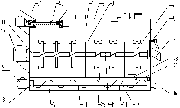
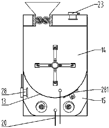
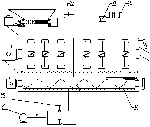
[0026] figure 1 , 2 , 3, 4, the present invention includes kettle body 1, kettle cover 2, compartment plate 3, first agitator 4, discharge valve 5, first discharge port 6, second agitator 7, second shaft seal Device 8 , first motor reducer 10 , first shaft seal device 11 , tank bottom filter plate 13 , first reaction chamber 14 , second reaction chamber 15 . The first reaction chamber 14 is provided with a feed port directly connected to the discharge port of the above crusher for feeding the crushed food waste and microbial strains. The first reaction chamber 14 is provided with a first discharge port. 6. It is used to discharge the decomposed material of the biochemical reaction of food waste. The first reaction chamber 14 is provided with a filter plate 13 at the bottom of the tank, and the filter plate 13 at the bottom of the tank is provided with holes, grooves or gaps for the leachate of the material to leak to the second Reaction chamber 15. The compartment plate 3 d...


PUM


Abstract

The invention discloses a stirring kettle type reactor which comprises a kettle body, wherein the inner cavity of the kettle is divided into a first reaction chamber and a second reaction chamber through a groove bottom filter plate; the inner cavity of the first reaction chamber is divided into more than two grooves by groove partition plates; a through hole is formed in the groove bottom filterplate at the groove on the most right side; a moveable insertion plate component is mounted at the through hole; the first reaction chamber is internally provided with a first stirrer; the first stirrer comprises a stirring shaft and a plurality groups of stirring paddle groups which are sequentially mounted on the stirring shaft along an axial direction; the stirring paddle groups are composed ofa plurality of stirring paddles which are distributed around a radial direction of the stirring shaft; the second reaction chamber is internally provided with more than one second stirrer; and the second stirrer is a spiral stirrer. The stirring kettle type reactor is adopted for on-site resource biochemical treatment on kitchen wastes in residential areas, the kitchen wastes can be collected, crushed, directly biologically treated and processed into organic fertilizers on site, resource recycling can be achieved, capacities and amounts can be reduced, wastes can be turned into wealth, the environment can be improved, equipment structures are reasonable, techniques are advanced, the biochemical treatment efficiency is high, the floor space is small, and no sewage filtering equipment is used.

Description

technical field [0001] The invention relates to the technical field of food waste resource treatment, in particular to a stirred tank reactor for biochemical treatment of food waste. Background technique [0002] At present, the kitchen waste from households in residential areas in many cities and towns has not been sorted and placed. Kitchen waste and domestic waste are mixed into garbage bags and placed in garbage bins in residential areas. The transfer station pours it into the compressor, and after compression, it is loaded into a large-tonnage garbage truck and transported to the suburban garbage treatment center for bag breaking, sorting, magnetic separation, composting and many other garbage treatment processes. Sorting is difficult, the working environment emits a bad smell, and there are many processes and a long time, which increases the degree of corruption of meal waste. A large amount of household waste cannot be disposed of in time due to lack of sorting facil...

Claims


Application Information

Patent Timeline
Patent Type & Authority Applications(China)
IPC IPC(8): C05F17/907C05F17/964
CPCY02W30/40
Inventor 刘江河徐伟张浩天刘洋莉
Owner 湖北安步环境技术研究有限公司
Learn More