A microstrip antenna array decoupling structure and method, and a microstrip antenna array using the structure

A microstrip antenna and array technology, applied in the field of microstrip antenna array and microstrip antenna array decoupling structure, can solve the problems of complex structure, large size, unit gain decline, etc., and achieve excellent unit radiation performance and good radiation pattern. , the effect of high unit gain

Active Publication Date: 2022-03-25
常州安塔歌电子科技有限公司
View PDF0 Cites 0 Cited by
  • Summary
  • Abstract
  • Description
  • Claims
  • Application Information

AI Technical Summary

Problems solved by technology

However, the current mainstream decoupling schemes have problems such as complex structure, large size, narrow bandwidth, and affecting antenna radiation performance.
For example, literature ["Microstrip antennas integrated with electromagnetic band-gap (EBG) structures: A low mutual coupling design for array applications," F. Yang and Y. Rahmat-Samii, "IEEE Trans. Antennas Propag.", Vol. 51, October 2003] Proposed Electromagnetic Band Gap (EBG) structure and literature ["Planar soft surfaces and their application to mutual coupling reduction," E.Rajo-Iglesias, et al., "IEEE Trans. Antennas Propag.", Vol. 57, December 2009] The soft surface (Soft Surfaces) structure proposed can prevent the surface wave propagation between the microstrip antenna elements, thereby achieving mutual coupling suppression, but its structure is complex and the size is large, and it cannot be placed in the microstrip at close range Applications in antenna arrays; literature ["Mutual coupling reduction between very closely spaced patch antennas using low-profile folded split-ring resonators," A. Habashi, et al., IEEE Antennas Wireless Propag. Lett., Vol. 10, 2011] and ["Reducing mutual coupling of closely spaced microstrip MIMO antennas for WLAN application," J.Ouyang, et al., "IEEEAntennas Wireless Propag. Lett.", Vol. 10, 2011] The proposed Defective Ground (DGS) structure can eliminate closely spaced Coupling between microstrip antenna elements, but its decoupling bandwidth is extremely narrow, and due to the radiation generated by the floor slit, the back lobe of the pattern is large, and the unit gain decreases
Literature ["Mutual coupling suppression between two closely spaced microstrip antennas with an asymmetrical coplanar strip wall," H. Qi, et al., "IEEE Antennas Wireless Propag. Lett. ", Vol. 15, 2016] through metal walls and parasitic stubs to block and offset the coupling between microstrip antenna elements placed at close distances, but the metal wall will greatly increase the height of the entire antenna system, which is not conducive to practical applications

Method used


Image

  • A microstrip antenna array decoupling structure and method, and a microstrip antenna array using the structure
  • A microstrip antenna array decoupling structure and method, and a microstrip antenna array using the structure
  • A microstrip antenna array decoupling structure and method, and a microstrip antenna array using the structure

Examples


Embodiment 1

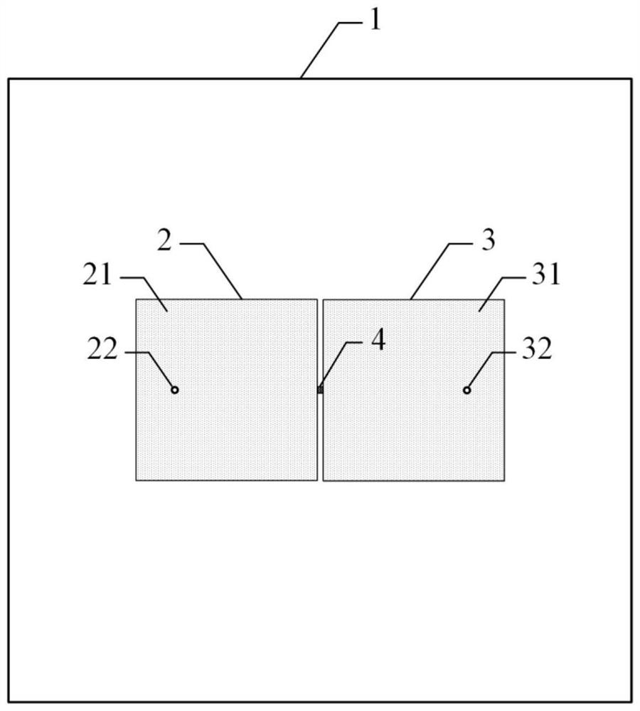
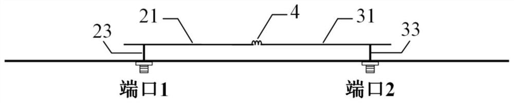
[0031] refer to figure 1 with figure 2 , the microstrip antenna array decoupling structure of the present invention, wherein the microstrip antenna array includes a metal floor 1 and two microstrip antenna units arranged above the metal floor 1, that is, the first microstrip antenna unit 2 and the second microstrip antenna unit 3. There is a distance between the two. The decoupling mainly depends on the decoupling component 4 connecting the first microstrip antenna unit 2 and the second microstrip antenna unit 3. In this embodiment, the decoupling component 4 uses a lumped inductance .

[0032] The structure, size and material of the first microstrip antenna unit 2 and the second microstrip antenna unit 3 are exactly the same, and the first microstrip antenna unit 2 includes a first metal patch 21, a first feed point 22 and a first feed The probe 23 , the second microstrip antenna unit 3 includes a second metal patch 31 , a second feeding point 32 and a second feeding probe...

Embodiment 2

[0039] Such as Image 6 It is the structural representation of embodiment 2. Compared with Embodiment 1, the arrangement of the units in Embodiment 2 has changed, and the specific differences are: the position of the first feed point 22 is close to the right side of the first metal patch 21; the position of the second feed point 32 The position is close to the left side of the second metal patch 31 . In this arrangement, decoupling can still be achieved by connecting a decoupling inductor.

Embodiment 3

[0041] Such as Figure 7 It is the structural representation of embodiment 3. Compared with Embodiment 1, the unit arrangement form of Embodiment 3 has changed, and the specific difference is that: the first microstrip antenna unit 2 and the second microstrip antenna unit 3 are changed from the center-symmetrical arrangement in Embodiment 1 to The arrangement is symmetrical in translation, that is, the first feed point 22 and the second feed point 32 are respectively close to the left side (or right side) of the first metal patch 31 and the second metal patch 32 . In this arrangement, decoupling can still be achieved by connecting a decoupling inductor.


PUM


Abstract

A microstrip antenna array decoupling technology, comprising: a metal floor; first and second microstrip antenna units; and a decoupling component connected between the first and second microstrip antenna units. The decoupling component may be a lumped inductor or an inductive metal branch. The invention realizes decoupling between tightly coupled microstrip antenna units through a novel decoupling component. Compared with the traditional decoupling scheme, the decoupling component proposed by the present invention has the advantages of simple structure, small size, low cost, broadband, and excellent unit radiation performance, and is suitable for decoupling of microstrip antenna arrays or MIMO systems.

Description

technical field [0001] The invention belongs to the technical field of antennas, and in particular relates to a decoupling structure and method of a microstrip antenna array and a microstrip antenna array adopting the structure. Background technique [0002] In array antennas and multiple-input multiple-output (MIMO) antenna systems, the mutual coupling between antenna elements will seriously deteriorate the radiation performance of the array antenna and the diversity performance of the MIMO system. Therefore, realizing the decoupling between antenna elements placed in close distance is very important for the design of array antenna or MIMO system, which can greatly improve the radiation and diversity performance of the antenna. However, the current mainstream decoupling schemes have problems such as complex structure, large size, narrow bandwidth, and affecting antenna radiation performance. For example, literature ["Microstrip antennas integrated with electromagnetic band...

Claims


Application Information

Patent Timeline
Patent Type & Authority Patents(China)
IPC IPC(8): H01Q1/38H01Q1/48H01Q1/50H01Q9/04H01Q21/06
CPCH01Q1/38H01Q1/48H01Q1/50H01Q9/0407H01Q21/065
Inventor 孙利滨张志军
Owner 常州安塔歌电子科技有限公司
Why Eureka
Try Eureka