
CO2 gas protection welding wire suitable for ultra-low thermal input automatic welding and manufacturing method thereof

A gas shielded welding wire, automatic welding technology, applied in welding/cutting medium/material, welding medium, manufacturing tools, etc., can solve the problem of poor fusion ability of groove edge, narrow welding process adjustment window, uneven distribution of weld metal, etc. problems, to achieve the effect of ensuring toughness and improving the overall performance of the joint

Inactive Publication Date: 2020-02-11
BAOSHAN IRON & STEEL CO LTD
View PDF8 Cites 0 Cited by
  • Summary
  • Abstract
  • Description
  • Claims
  • Application Information

AI Technical Summary

Problems solved by technology

[0006] like figure 1 As shown, for API 5LX70M pipeline steel pipes, low-alloy steel commonly used AWS A 5.18ER70S-G gas-shielded solid wire is used for automatic welding with ultra-low heat input of 0.25kJ / mm (shielding gas is 80%Ar+20%CO 2 ), due to the rapid cooling after welding, unevenly distributed strip martensite and a large number of clustered M-A components appear in the weld metal, which leads to a serious decline in its toughness, and the single value of impact energy at -10°C is even lower than 35J, the CTOD fracture toughness value is generally lower than 0.1mm, and some are lower than 0.05mm
[0007] In addition, 80%Ar+20%CO 2 The mixed gas has the characteristics of argon arc. Although the welding process is stable and the spatter is small, due to the characteristics of the argon arc plasma energy distribution center is high and the periphery is low, the fusion ability of the edge of the groove is poor during rapid welding under the requirement of ultra-low heat input. The probability of non-fusion defects is high, and the welding process adjustment window is very narrow

Method used


Image

  • CO2 gas protection welding wire suitable for ultra-low thermal input automatic welding and manufacturing method thereof
  • CO2 gas protection welding wire suitable for ultra-low thermal input automatic welding and manufacturing method thereof
  • CO2 gas protection welding wire suitable for ultra-low thermal input automatic welding and manufacturing method thereof

Examples


Embodiment 1-6

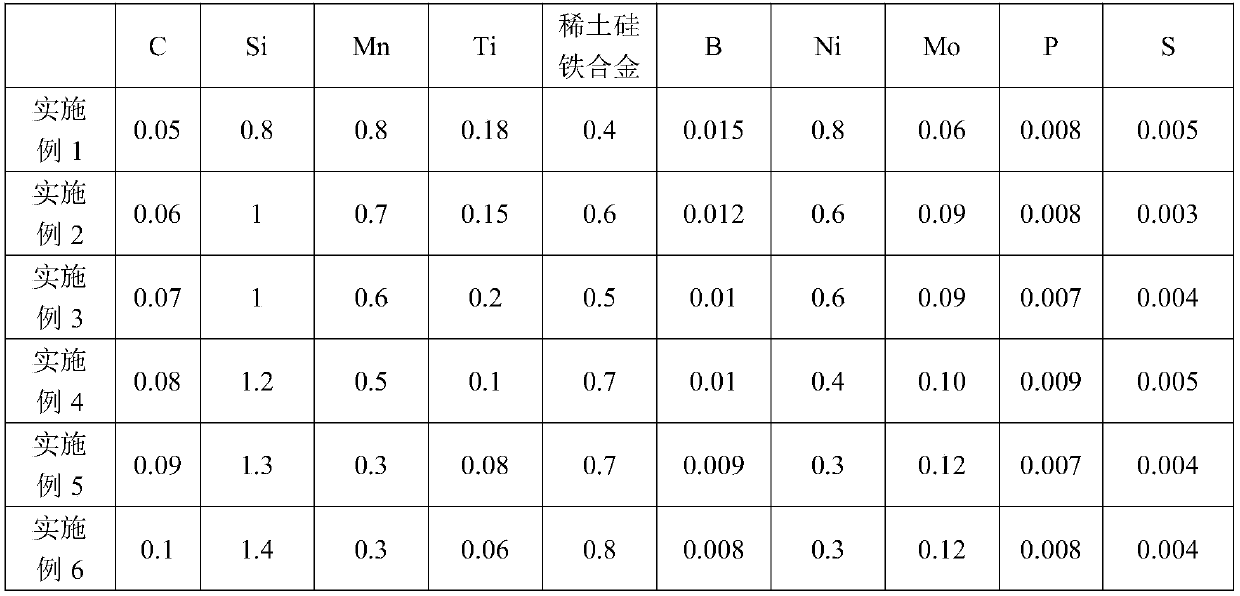
[0059] Table 1 has listed the CO that is suitable for ultra-low heat input automatic welding of embodiment 1-6 2 The mass percentage of each chemical element in the gas shielded welding wire.

[0060] Table 1. (wt%, the balance is Fe and other unavoidable impurities except P and S)

[0061]

[0062] Proportioning is carried out according to each chemical element listed in Table 1, the raw material after the proportioning is put into vacuum electric furnace smelting, the steel ingot after solidification is carried out rolling, drawing and layer winding, finally obtain the suitable ultra-thin of embodiment 1-6 CO for low heat input automatic welding 2 Gas shielded welding wire.

[0063] To verify the obtained CO 2 The welding performance of gas shielded welding wire, the CO of embodiment 1-6 2 Gas shielded welding wire is welded, the CO of embodiment 1-6 2In the all-position welding process of gas shielded welding wire, different welding process parameters are adopted ac...


PUM

PropertyMeasurementUnit
yield strengthaaaaaaaaaa
tensile strengthaaaaaaaaaa
yield strengthaaaaaaaaaa

Abstract

The invention discloses a CO2 gas protection welding wire suitable for ultra-low heat input automatic welding. The CO2 gas protection welding wire comprises, by mass percentage, 0.05-0.1% of C, 0.8-1.4% of Si, 0.3-0.8% of Mn, 0.06-0.2% of Ti, 0.4-0.8% of a rare earth silicon iron alloy, 0.008-0.015% of B, 0.3-0.8% of Ni, 0.05-0.15% of Mo and the balance Fe and other inevitable impurity elements. The invention further discloses a manufacturing method of the CO2 gas protection welding wire. The manufacturing method comprises the following steps that the raw materials are smelted in a vacuum electric furnace, rolling, drawing and layered winding are carried out on a solidified steel ingot, and the CO2 gas protection welding wire is obtained. The CO2 gas protection welding wire utilizes a tissue homogenization mechanism under the combined effect of chemical elements, so that the weld metal toughness formed by welding is ensured.

Description

technical field [0001] The invention relates to a welding wire and a manufacturing method thereof, in particular to a gas shielded welding wire and a manufacturing method thereof. Background technique [0002] MMA automatic welding has the advantages of high welding efficiency, good welding quality and convenient operation. It is a welding method commonly used in various industrial fields. Inert gas (such as Ar and He), active gas (such as CO 2 ) or mixed gas (Ar+O 2 , Ar+CO 2 or multiple gas mixtures). Among them, CO 2 Gas shielded welding has the advantages of fast welding speed, large penetration depth and low cost, and is widely used in the industry. [0003] Generally, the heat input range of solid wire melting electrode gas shielded automatic welding is 0.5~1.5kJ / mm, and the ultra-low heat input of 0.25kJ / mm belongs to the extremely harsh welding process conditions. Accelerated metal cooling and severe non-equilibrium solid-state phase transformation will have an...

Claims


Application Information

Patent Timeline
Patent Type & Authority Applications(China)
IPC IPC(8): B23K35/30B23K35/12B23K35/40
CPCB23K35/0261B23K35/3053B23K35/40
Inventor 刘硕
Owner BAOSHAN IRON & STEEL CO LTD
Learn More