System for generating center-frequency-variable high-speed linear frequency modulation based on phase-locked loop

A technology of linear frequency modulation signal and center frequency, which is applied in the field of radio frequency, can solve problems such as affecting the linearity of output frequency, difficult to correspond, and unable to meet the requirements of fast response indicators, so as to achieve the effect of ensuring the response speed

Active Publication Date: 2020-02-11
CHENGDU SINE SCI & TECH
View PDF7 Cites 0 Cited by
  • Summary
  • Abstract
  • Description
  • Claims
  • Application Information

AI Technical Summary

Problems solved by technology

[0008] The circuit based on the voltage-controlled oscillator to generate the linear frequency modulation signal has the following defects: 1) The characteristics of the voltage-controlled oscillator at high and low temperatures cannot be effectively compensated, and the circuit can only rely on the temperature compensation resistor to qualitatively determine the magnification of the operational amplifier The output voltage is roughly compensated, and the temperature change curve of the temperature compensation resistor is difficult to correspond to the change curve of the voltage-controlled oscillator.
The output frequency of the VCO will change under different ambient temperatures
As a result, the required linear frequency modulation signal frequency cannot be obtained accurately, and it is difficult to meet the increasingly higher performance requirements
And it brings great difficulty to the selection of temperature compensation resistor and the debugging of operational amplifier, which affects the production efficiency
2) Although the circuit structure is simple, the frequency is not locked due to the free oscillation method, resulting in poor phase noise and poor controllability of the output chirp signal, and it cannot be used as a frequency hopping source
Difficulty meeting increasingly high performance requirements
[0009] The circuit based on the phase-locked loop to generate the chirp signal has the following defects: 1) The essence of directly generating the chirp signal through the single-chip microcomputer control phase-locked loop belongs to digital synthesis, so there is a certain step in the frequency of the output signal, such as 1MHz step, which affects Linearity of output frequency
2) Although the circuit is controllable and the frequency is accurate, the response speed of the phase-locked loop is relatively slow, generally on the order of milliseconds, which cannot meet the index requirements for fast response. The fast response is generally on the order of microseconds, or even nanoseconds class
[0010] The circuit for generating chirp signals based on DDS has the following defects: 1) The essence of this circuit is direct digital frequency synthesis, so there is a certain step in the frequency of the output signal, such as 10KHz step, even if the step can be made very small, but still have some effect on the linearity of the signal
2) The DDS circuit itself is more complex, and consumes more power, and requires a higher reference clock, such as image 3 As shown, a phase-locked loop is used to generate the reference clock signal required by DDS
3) The chirp signal generated by DDS has a narrow bandwidth and poor spurious
4) The frequency of the chirp signal generated by DDS is very low, generally below 1GHz
5) Although the phase noise of the chirp signal generated by DDS is excellent, when there is a high frequency requirement, the frequency needs to be increased by frequency doubling or mixing, and frequency doubling will directly deteriorate the phase noise, and the phase noise of mixing It depends on the signal with poor phase noise, so when required by high frequency, the phase noise will not be better than the phase locked loop
[0011] To sum up, the above three traditional linear frequency modulation circuits have their own advantages and disadvantages, and it is difficult to meet the increasingly higher performance requirements without solving the defects.

Method used


Image

  • System for generating center-frequency-variable high-speed linear frequency modulation based on phase-locked loop
  • System for generating center-frequency-variable high-speed linear frequency modulation based on phase-locked loop
  • System for generating center-frequency-variable high-speed linear frequency modulation based on phase-locked loop

Examples


Embodiment Construction

[0028] The technical solution of the present invention will be described in detail below in conjunction with the accompanying drawings.

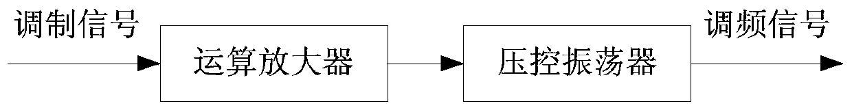
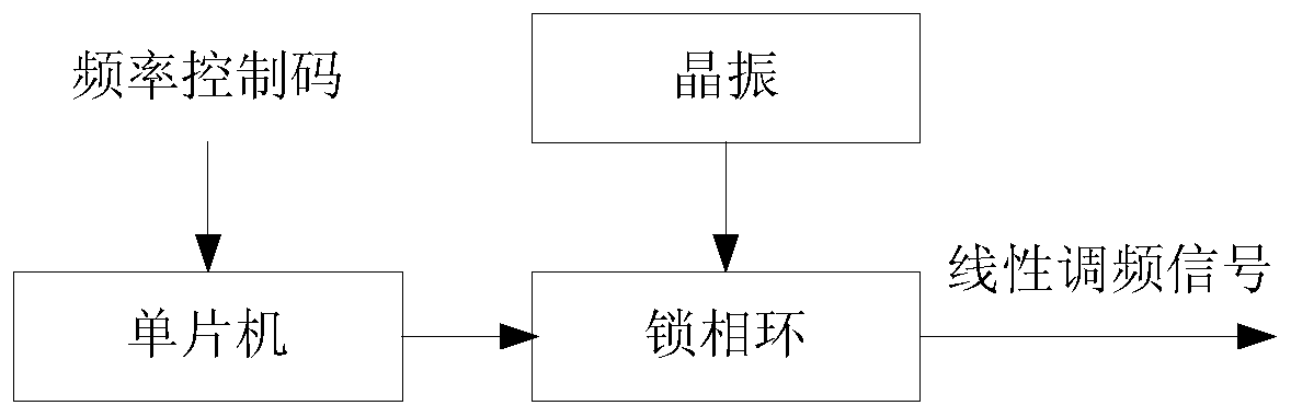
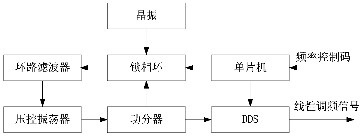
[0029] The system for generating a high-speed linear frequency modulation signal with a variable center frequency based on a phase-locked loop in the present invention, its principle block diagram is shown in Figure 4 , wherein, the system includes: an operational amplifier, a single-chip microcomputer, a phase-locked loop, a crystal oscillator, a loop filter, an adder, a voltage-controlled oscillator and a directional coupler, the operational amplifier is connected to the adder, and the single-chip microcomputer and the crystal oscillator are connected to the lock The phase loop is connected, the phase locked loop is connected with the adder through the loop filter, the adder is connected with the directional coupler through the voltage controlled oscillator, and the directional coupler is connected with the phase locked loop.

[0030] In ...


PUM


Abstract

The invention provides a system for generating a center-frequency-variable high-speed linear frequency modulation signal based on a phase-locked loop, and belongs to the field of radio frequency. Thesystem comprises an operational amplifier, a single-chip microcomputer, a phase-locked loop, a crystal oscillator, a loop filter, an adder, a voltage-controlled oscillator and a directional coupler. The operational amplifier is connected with the adder, the single-chip microcomputer and the crystal oscillator are both connected with the phase-locked loop, the phase-locked loop is connected with the adder through the loop filter, the adder is connected with the directional coupler through the voltage-controlled oscillator, and the directional coupler is connected with the phase-locked loop. According to the invention, the phase-locked loop is used to accurately lock the center frequency of the output chirp signal; the modulation signal and the direct current signal output by the phase-locked loop are superposed through the adder; the size of the linear frequency modulation signal and the sweep frequency bandwidth are controlled, the single-chip microcomputer is used to control the switching of the center frequency, the purposes of ultra wide band and adjustable center frequency are achieved, the response speed of the sweep frequency signal is ensured by using a direct driving mode,and higher and higher performance requirements can be satisfied.

Description

technical field [0001] The invention relates to the radio frequency field, in particular to a system for generating high-speed linear frequency modulation signals with variable center frequency based on a phase-locked loop. Background technique [0002] Frequency source generation is an important microwave technology, and almost all radio frequency systems use frequency sources. In recent years, with the rapid development of communication technologies such as digital wireless communication, radar, and radio and television, the performance requirements for frequency sources have also gradually increased. Among them, the chirp signal is an important frequency source technology. How to generate a high-speed and stable chirp signal is a problem that radio frequency engineers and engineering applications must face and solve. [0003] At present, the traditional three kinds of circuits for generating chirp signals are specifically: a circuit for generating chirp signals based on ...

Claims


Application Information

Patent Timeline
Patent Type & Authority Applications(China)
IPC IPC(8): H03L7/18
CPCH03L7/18Y02D30/70
Inventor 姚宗诚黄涤生王清文吴义华
Owner CHENGDU SINE SCI & TECH
Why Eureka
Try Eureka